I'm going to be giving you engineering facts about the design of the two different rims and how the tire inter reacts with it. I am also going to be going over the science behind tires and traction, not opinions.
I have emailed several tire manufacturing companies asked them some serious questions on how a ct runs on a motorcycle and if they would ever consider doing a side by side comparison. The answers I got back would astound many people. To answer the question if they would ever do a side by side comparison was always no, with the exception of Cooper tires but Cooper tires won't do it because of insurance regulations. Cooper tires are headquartered in England where it is illegal to use a car tire on a motorcycle. One of the reasons why no tire company would ever do a side by side comparison is for safety reasons. The rider of the bike cannot know which tire is on the bike during the tests. If the rider is unaware of the tire it is it could create a catastrophic condition that could harm the rider and others. They are not willing to take that risk.
As to where I have gotten my engineering facts from:
TJ Tennent - Lead motorcycle tire engineer for Bridgestone\Firestone
Virginia Gallant - Tire engineer from Dunlop\Goodyear
Tire and Rim Association - Joe Pacuit
Sukoshi Fahey - Lead Motorcycle tire Developer from Cooper\Avon Tires
I have also received emails back from both Metzler and Hankook but not from anyone in particular.
Some of the reading I have been doing is "The Theory of Ground Vehicles" by Jo Yung Wong and "Motorcycling Handling and Chassis Design" by Tony Foale. “The Pneumatic Tire” from the National Highway Traffic Association 2006 edition.
I have spent about 2 hours on the phone with TJ Tennent learning about how tires are designed and manufactured and some of the chemical make-up of the tires. The exact ingredients of what and how much are highly classified and are not given out. I also spent about an hour on the phone with Joe Pacuit discussing the rim’s design an function. I have also spoken with Sukoshi Fahey for about an hour over the phone.
The Tire and Rim Association sets the standard to which all tires and rims are to be designed to in the USA. I have managed to get Joe Pacuit from the Tire and Rim Association to give me a copywrited and patented, proprietary trade secrets on that only the tire and rim engineers should have. This was given to me on the understanding that I will not publish nor distribute these pages. I can however, tell you what the design measurements are suppose to be for each of the respective tires and rims.
During the time on the phone with Joe Pacuit he told of the four separate and different properties that hold a tire on the rim. You have one pneumatic property, and three mechanical properties. Thinking I was smart, told him I knew what the pneumatic property was, air pressure, and I could figure out two of the three mechanical properties. I said one would be the circumference of the rim and the other would be the width of the rim. He told me I only got one of the mechanical properties correct, the circumference of the rim. The width of the rim has no bearing on how it holds the respective tire on the respective rim. You can put a 4 ½” wide tire on a 5” rim or a 5” tire on a 4 ½” rim just as long as you get the bead to be properly seated it will stay on. The other two properties are generated by the design of the rim’s shape.
As a tire spins, the centrifugal force generated makes the tire’s bead seat to want to pull from the rim’s bead seat and during cornering, the lateral loads placed on the tires want to push the tire away from the bead flange. As alluded to, in the design of the rims there are two things other than just the circumference of the rim and the air pressure that help hold the tire on. They would be the bead hump, and the bead lock. The bead hump helps keep the tire help against the bead flange and the bead lock helps keep the tire from pulling away from the bead seat.
The bead lock is formed as the shape of the face of the bead flange and how the bead flange meets up with the radius from the bead seat to the bead flange. On a car tire/rim combination has a 6.5mm radius. On a motorcycle tire/rim combination has a 2.5mm radius. The bead flange on a car tire is 17.5mm tall and the bead flange has a radius of 9.5m radius on the face. On a motorcycle the bead flange is only 14mm tall and it has one radius in the middle of 12.5mm and a 3.0mm radius on the very top of the face.
The bead hump is quite different in shape and size from a car rim to a motorcycle rim. The bead hump is a little larger on a motorcycle rim versus a car rim because of the extra forces generated while the motorcycle is cornering. The bead hump is placed in a VERY critical location on both rims. On a car rim it is 21mm from the bead flange to the center point of the bead hump. On a motorcycle it is placed at 16mm from the bead flange to the center point of the bead hump. Why this is critical, is the respective tire that fits the respective rim will have a matching size bead seat of both the rim and the tire. So by placing a 21mm bead seat (car tire) in a spot only allocated for 16mm. (Motorcycle rim) the car tires bead seat is sitting on the bead hump not down by it allowing the bead hump to help hold the tire on the rim. Thus this where and how a car tire can dismount from a motorcycle rim.
Here is an AutoCAD drawing I have done to help with explaining the dimensions and how the tires and rims interact with each other:
![Image]()
As far as rim widths, they are the same for both the car rim and the motorcycle rim with the following exception. The 5 ½” rim, the car rim is only .5mm smaller than a motorcycle rim and there is no 7” or 7 ½” wide rims for motorcycles.
The Bead Flange (the area of the rim where the bead of the tire seats against the side of the rim)
Car Rim 17.5mm (.689")
Motorcycle Rim 14mm (.551")
The Bead Seat (the area where the tire sits on the rim in between the bead flange and the bead hump. The bead hump is what helps keeps the bead of the tire against the flange of the rim)
On a Car Rim it is 21mm wide with a 5* positive slope.
On a Motorcycle Rim it is 16mm wide with a 5* positive slope.
The lower inside corner of the rim where the bead flange and bead seat meet for the bead to interlock the tire in to the rim also known as the bead lock (the respective tire will have a matching size radius):
On a Car Rim it has a 6.5mm (.256”) Radius
On a Motorcycle Rim it is 2.5mm (.098”) Radius
The outer bead flange radius (the top outer edge of the rim):
On a Car Rim it has 9.5mm (.374”) radius
On a Motorcycle Rim have both a 12.5mm (.492”) and a 3mm (.118”) Radius
Rim Diameters (Tolerances: For Motorcycles +/- .015" For Cars +/- .04")
15"
CT 14.968"
MT 15.08"
16"
CT 15.968"
MT 15.978
17"
CT 17.189"
MT 17.08
Now that we covered the rim, let’s get into the design differences between the two types of tires. This will be long but worth the read.
Steering:
First, let’s see examine the different factors and forces placed on a car tire:
![Image]()
Since the precise effective location at which the road applies forces to the tire is unknown and the origin of the tire axis system is arbitrarily defined by the wheel and road geometry, three forces (Fx, Fy, and Fz) and three moments (Mx, My, and Mz) are required to define the road’s action upon the tire.
Each of the three forces acts along its associated axis in the tire coordinate system. For example, Fx acts along X′. The positive direction for each force is the same as the positive direction for its associated axis as indicated above. The three forces are defined as follows.
Longitudinal force, Fx, is the force of the road on the tire along the X′-axis. It accelerates or decelerates the vehicle dependent on whether the tire is driven or braked. If Fx is positive, the tire is driven, and Fx is called driving force. If Fx is negative, the tire is braked, and Fx is called braking force.
Lateral Force, Fy, is the force of the road on the tire along the Y′-axis. It forces the vehicle to move to the left or right dependent on whether the tire is steered and/or cambered to the left or right.
Normal force, Fz, is the force of the road on the tire along the Z′-axis. It is the contact force between the road and tire. By definition, it is negative.
Each of the three moments acts about its associated axis in the tire axis system. For example, Mx acts about X′. The right hand rule applies. The positive sense for each moment is clockwise about the positive branch of its associated axis when looking away from the tire axis system origin along the positive branch of the axis. This is shown above. The three moments are defined as follows.
Overturning moment, Mx , is the moment about the X′-axis. It accounts for the effect of left-to-right displacement of the point of action of the normal force with respect to the contact center. Mx influences camber behavior.
Rolling resistance moment, My, is the moment about the Y′-axis. It accounts for the foreaft displacement of the point of action of normal force with respect to the contact center. My is somewhat misnamed, as it has little to do with rolling resistance.
Aligning moment, Mz, is the moment about the Z′-axis. It accounts for the point of action of the shear forces, Fx and Fy, within the road plane.
The tire and wheel are also subjected to moments due to gyroscopic and angular accelerations that occur during dynamic operation.
And now a Motorcycle tire. They are much the same as a car but since the motorcycle MUST lean to turn so it creates some new equitation’s and omits the slip angle:
![Image]()
The basis of the MF-MCTire model is the Magic Formula. Research proves that the motorcycle version of this formula is able to accurately describe the characteristics of the forces and moments generated by a motorcycle tire. The model surrounding the Magic Formula has been derived from an automobile tire model, which is therefore suited especially for the slip and camber angle range of these tires. As the camber angle range is significantly larger for motorcycle tires than for automobile tires, the model is known to be less accurate when it is evaluated under large camber angles. Furthermore, for the processing of the measurements several assumptions are made which negatively influence the accuracy. In this chapter the weak points and error sources of the MF-MCTire model are revealed and possible solutions are mentioned. In this chapter the results of an elaborate measurement program are presented. These measurement results are used to elaborate the solutions and to evaluate their correctness.
The axis systems of the tire model play an important role. Therefore the definitions of the most important axis systems are again given. The C-axis system is fixed to the wheel carrier with the longitudinal Xc-axis parallel to the road and in the wheel plane (xc-zc-plane). The origin O of the C-axis system is the wheel center. The origin of the W-axis system is the road contact point C defined by the intersection of
the wheel plane, the plane through the wheel spindle and the road tangent plane. The xw-yw-plane is the tangent plane of the road in the contact point C, and it defines the camber angle ° together with the normal nr to the road plane (xw-yw-plane). Furthermore, the forces and moments are described in both axis systems. Therefore all forces and moments have a c or w index, which points out with respect to which reference axis system they are defined. The implementation of the MF-MCTire model by means of the Standard Tire Interface (STI) is described. Each time step, several kinematic parameters are retrieved from the wheel center (the C-axis system) and used as an input for this interface. Furthermore the interface returns the forces and moments in the C-axis system as a feedback to the wheel center.
The processing of the input parameters within the STI is schematically depicted in this diagram.
![Image]()
First of all the contact routine uses the position and orientation of the wheel and the road profile to determine the exact position of the contact point. This point is used as the origin of the Waxis system. In this origin the input variables of the Magic Formula, the vertical load Fzw, the longitudinal slip ·, the side slip angle ® and the camber angle ° are determined by this routine. With these input parameters known, the Magic Formula is evaluated and the forces and moments in the contact point are determined. As these forces and moments are applied to the vehicle model at the wheel center, they are converted from the W- to the C-axis system. As said, the loop with the vehicle model and the STI is evaluated at each time step of the vehicle simulation.
Next to the simulation loop, also the measurement line is depicted in figure 4.2. In contradiction to the simulation loop this line is only evaluated once. First of all, the tire behavior is experimentally determined by the Delft-Tire Test Trailer (DTT). During tests the test trailer has a certain forward velocity and the tire is pushed against the road at various loads, orientations and motion conditions. During these tests, all forces and moments are measured at the wheel center (the C-axis system). As the Magic Formula is evaluated in the W-axis system, the M-Tire software is used to convert the measurements to the contact center. Finally, the MF-Tool software is used to fit the Magic Formula parameters to the measured forces and moments. This leads to a set of parameters that represents one single tire. This set of parameters and some general tire parameters are captured in a tire property file which is used by the STI during each time step of a vehicle simulation, in order to describe the momentary tire behavior.
![Image]()
![Image]()
![Image]()
Car tires are steered by being turned. This is what as known as the slip angle. The slip angle will make the tread area distort as it turns.
![Image]()
This is better known as tire squirm. Since CT share an axle (beam) the lateral forces generated in steering are shared between the two tire thus they do not need to be designed the lateral forces that a MT gets as shown in these graphs:
![Image]()
![Image]()
![Image]()
MT is steered by leaning (camber angle). By introducing another axis in the steering, camber angle, which also creates camber thrust. it creates a different type of equation to determine the lateral forces applied to the tire thus any math done on the CT is invalid for a MT.
Load Ratings:
CT on designed for a specific amount of load rate. Since the CT can be put on any wheel on any corner of the vehicle the acceleration loads and braking loads are not as specific as to the tire and to its load rating capacity. Since MT are designed specifically for either the front or rear, the extra load rating of either the acceleration (for rear) or braking (for front) loads are taken into consideration. So the load ratings for motorcycle tire are a little different than a car tire. You should always consult the owner’s manual for the amount of load rating you need. The load rating is not just for the weight of the bike, it also includes the braking and acceleration forces. Now if we do some basic math on load ratings for those that say the CT designed to handle "allot more weight". An average car with a high GVWR of about 4000 lbs will be used in this example. The Goldwing was a GVWR of 1200 lbs (without the acceleration or braking load rating). Since all CT are not designed for a specific place on the vehicle the must be able to share the load equally thus giving the tire a maximum of 1000 lbs per tire. Since the MT is designed for a specific tire location, they are designed to handle a certain amount weight from the bike. The Goldwing (and most bikes) have a weight distribution of 40/60 (front/rear). So if we take the GVWR and multiply by 60% (.6) we find that the Goldwing MT can handle 720 lbs of dead weight. Again this DOES NOT take into considerations of the acceleration loading on the rear tire. So the CT can handle only 280 extra lbs of dead weight versus the MT.
Tread designs:
Race tracks are pieces of exceptionally well maintained pothole-free road surfaces, with special crews that clean up oil spills and wipe off rain water with squeegies -- and thus tires for racing use often do not have any tread design at all or one with minimum treading (to maximize the rubber-to-ground interface).
By comparison, a modern street tire has to deal with a long list of possible road-surface contaminants and irregularities, including water (rain, snow, slush), oil, automatic transmission fluid (ATF), spilled diesel fuel, sand, dirt, soil, gravel, loose asphalt, ridged concrete, slab-gaps and expansion-fills, bumps, pits, potholes, reflectors, cracks (and grass growing from the cracks), tar patches, etc. The list is almost endless. To help compensate for these irregularities, the carcass design of street/touring tires are different from those of track tires, including the inclusion of tire treads (in the USA, DOT-mandated). Please note that not all treads are designed equal!
In the tire industry, the grooves cut or formed in tires are called "sea" and the ridges that border the grooves and the raised sections between the grooves are called "land". Different manufacturers have different land and sea designs, and even vary the land-sea design between tires in their own line-ups based on the intended use. Note that some designs have specific advantages over others.
For example, if the front tire has grooves that go around the very center of the tire for it's entire circumference (center line groove/grooves), then the tire's center-line groove's sea area will have a tendency to track concrete that has ridges running in the same direction as traffic, or the metal grating on open-grated bridges (like some draw bridges) -- and can induce a very severe front end wobble as a result, which is disconcerting to say the least. To avoid this, many manufacturers redesigned the center line to go back and forth across the tire slightly (an oscillating center line design), while others avoid a centerline groove all together. On the other hand, centerline grooves provide a benefit when riding in heavy rains, slush and slurry, as they help maintain road contact. It's a trade-off, depending on where you live and what kinds of roads you tend to face.
Similarly, tires designed specifically for off-road use will have tread designs with wide seas and very large land-to-sea height differences to compact loose soil and sand under the tire to maximize traction on that kind of surface. Enduro tires, which are designed to be used on packed dirt roads and other semi-improved surfaces will have yet another design over those of conventional street tires, designed to increase the foot-print of the tire to the road to help offset slippage.
Construction:
The design and construction of the carcass determine, to a great extent, the characteristics of the tire. Among the various design parameters, the geometric dispositions of layers of rubber-coated cords (plies), particularly their directions, play a significant role in the behavior of the tire. The direction of the cords is usually defined by the crown angle, which is the angle between the cord and the circumferential center line of the tire. As shown here.
![Image]()
When the cords have a low crown angle, the tire will have good cornering characteristics, but a harsh ride. On the other hand, if the cords are at right angle to the centerline of the tread, the tire will be capable of providing a comfortable ride, but poor handling performance.
A compromise is adopted in a bias-ply tire, in which the cords extend diagonally across the carcass from bead to bead with a crown angle of approximately 40*. A bias-ply tire has two plies (for light-load tires) or more (up to 20 plies for heavy-load tires). The cords in adjacent plies run in opposite directions. Thus, the cords overlap in a diamond-shaped (criss-cross) pattern. In operation, the diagonal plies flex and rub, thus elongating the diamond-shaped elements and the rubber-filler. This flexing action produces a wiping motion between the tread and the road, which is one of the main causes of tire wear and high rolling resistance. Generally there at least 6 plies but that depends on the tire manufacturer. With plies running from bead to bead and being more plies, it makes for stiff sidewalls.
The radial-ply tire, on the other hand, is constructed very differently from the bias-ply tire. It was first introduced by Michelin in 1948 and has now become dominant for passenger cars and trucks and increasingly for heavy-duty earth-moving machinery. However, the bias-ply tire is still in use in particular fields, such as cycles, motorcycles, agricultural machinery, and some military equipment. The radial-ply tire has one or more layers of cords in the carcass extending radially from bead to bead, resulting in a crown angle of 90*. A belt of several layers of cords of high modulus of elasticity (usually steel or other high-strength materials) is fitted under the tread. The cords in the belt are laid at a low crown angle of approximately 20*. The belt is essential to the proper functioning of the radial-ply tire. Without it, a radial-ply carcass can become unstable since the tire periphery may develop into a series of buckles due to the irregularities in cord spacing when inflated. For passenger car tires, usually there are two radial plies in the carcass made of synthetic material, such as rayon or polyester, and two plies of steel cords and two plies of cords made of synthetic material, such as nylon, in the belt. For the radial-ply tire, flexing of the carcass involves very little relative movement of the cords forming the belt. In the absence of a wiping motion between the tire and the road, the power dissipation of the radial-ply tire could be as low as 60% of that of the bias-ply tire under similar conditions, and the life of the radial-ply tire could be as long as twice that of the equivalent bias-ply tire. For a radial-ply tire, there is a relatively uniform ground pressure over the entire contact area. In contrast, the ground pressure for a bias-ply tire varies greatly from point to point as tread elements passing through the contact area undergo complex localized wiping motion. Note: that MT that is of the radial design has 4-6 plies run from bead to bead to give a stiffer sidewall that a MT requires. Most CT nowadays are of the radial ply design while most MT are still of the bias ply design.
Tire Beads.
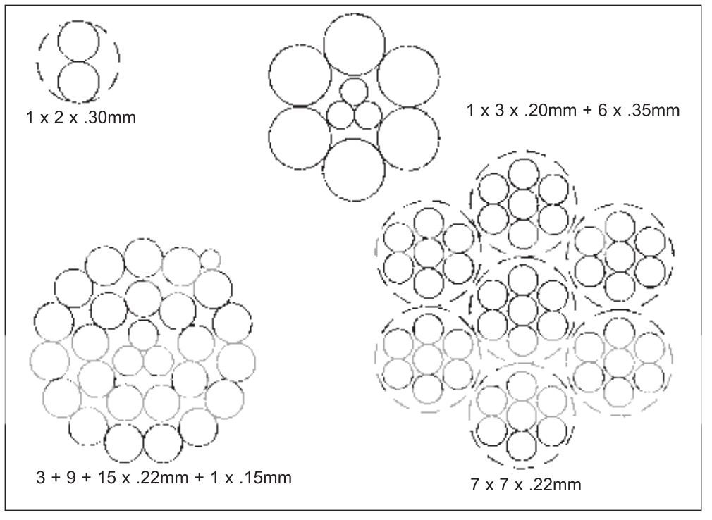
We need to discus some terminology first. The terminology used for defining tire cords comes from the textile industry. Here is some of the common vocabulary.
![Image]()
Length and direction of lay
The sequence in both the length and direction follows the manufacturing sequence. For example:
3 + 9 + 15x0.22 + 0.15 5/10/16/3.5 SSZS
5S: lay length and direction of strand 3x0.22
10S: lay length and direction of strand 9x0.22
16Z: lay length and direction of strand 15z0.22
3.5S lay length and direction of wrap.
![Image]()
Product type
Several types of cord products are available based on variations in the manufacturing and twisting procedures. Regular cord – standard cord production in which the lay direction in the strands is opposite to the lay direction in closing the cord. This product is easy to produce, cost effective, and processes well in the tire factory.
Lang’s lay cord (LL) – cord in which the lay direction of the strands is the same as the lay direction in closing the cord. High elongation cord (HE) is a Lang’s lay cord in which the strands are loosely associated and moveable with respect to each other. This allows the cord to be stretched substantially and gives useful cut protection when used in the top belt of radial truck tires and impact resistance in the rock penetration zone of earth mover and mine tires.
Open cord (OC) - A cord in which the filaments are loosely associated and moveable relative to each other. This permits rubber to penetrate into the cord to maximize adhesion to the filaments and to prevent moisture wicking along the cord that could result in steel corrosion. This cord is difficult to process with standard calendering equipment as excessive tension during processing can close the cord resulting in void formation along the cord. Open construction cord has been the subject of numerous patents for various production techniques and cord designs. Bekaert offers a BETRU™ cord which is less sensitive to calender tensions and cord wicking.
Compact cord (CC) – cords are produced in a single compact bundle in which the filaments have mainly linear contact with each other. This construction is useful in applications such as for the carcasses of heavy-duty radial tires where severe fretting fatigue can occur at crossover points in a standard cord.
Tire cords are built up from yarns which in turn come from filaments. Filaments from a production spinerette are gathered together, slightly twisted, and placed on “beams” for further processing. A common hemp rope shows this construction, but on a larger scale.
![Image]()
The filaments are twisted “Z” into yarns and the yarns are back-twisted “S” to form a cord. The size of a tire filament, yarn, or cord is measured by its weight per unit length - linear density or “denier” (denier is the weight in grams of 9000 meters) or “decitex” (weight in grams of 10,000 meters). Textile cords are identified by their yarn denier and their construction. Thus a 940/2 8x8 nylon cord is formed from 2 - 940 decitex yarns twisted separately at 8 turns per inch and then back-twisted together at 8 turns per inch to form the cord. A 1650/3 10x10 rayon cord would comprise 3-1650 denier yarns twisted at 10 turns per inch separately and back-twisted together at 10 tpi. For a given material, use of higher denier yarns or more yarns per cord result in a higher breaking strength of the cord.
Here is a lists representative of constructions and properties of some steel cords used in various radial tires. Notice the breaking load value, cord diameter and the lay direction of the bead used in a motorcycle tire versus those used in a light truck and passenger car tire:
![Image]()
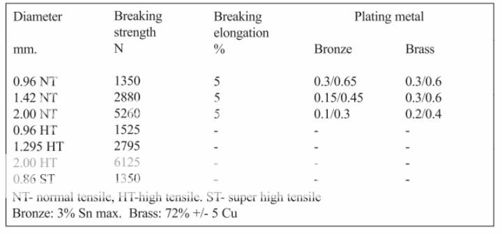
Steel bead wire is not considered a cord since it is not constructed from twisted filaments. In terms of steel cord nomenclature, a bead wire would be considered a filament. Tire beads are made from single steel wires of larger diameter. They are manufactured by several processes, including tape-wound beads, single-wire wrapped beads, or cable beads. Each type has certain performance or cost advantages. A similar wire is used in all of these constructions. The wire diameter, number of wires (or turns), and type of steel will depend on the size and load carrying requirements of the tire. Beads are designed with an over-pressure blow-off safety factor, load distortion resistance, rim slippage resistance, and resistance to bead breakage during mounting. Wires for beads are supplied as regular or high strength steel, in various diameters, and bronze or brass coated for adhesion. This table lists the typical properties of some standard bead wires.
![Image]()
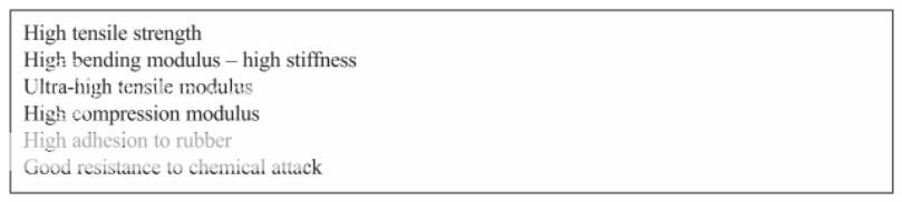
Steel cord adhesion
For maximum long-term durability the steel cord used in radial tires must have a high level of rubber-to-brass adhesion and a high degree of resistance to corrosion caused by water entering the tire through road cuts and penetrating to the belt cord. Poor performance in either area can result in reduced tire service life. Thus, prevention of loss in adhesion in steel-belted radial tires is a prime consideration for tire engineers. The exact mechanism of brass-to-rubber adhesion has been the subject of much study and conjecture. Basically, it is conjectured that a bond is formed between the polar metals and the non-polar rubber during vulcanization with sulfur by formation of a Cu-S- Rubber bond, as idealized in this chart.
![Image]()
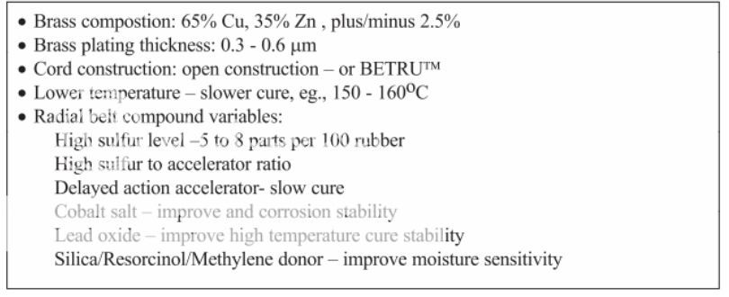
However, this bond can readily be converted to CuS with loss of adhesion under some circumstances. There are also indications that optimum bonding involves interfacial layers of oxides and sulfides of both copper and zinc. Bond durability is tested by measuring bond strength after various aging times and under various conditions: Dry heat aging, steam aging, aging in high humidity, and salt bath immersion. The rubber coverage of the wire after testing is regarded as equally important as the retained bond strength of the rubber compound. Corrosion (rust) of steel can destroy both the adhesive bond and the wire itself. Cord construction, brass composition, brass plating thickness, rubber compound composition, tire curing and storage conditions can all affect wire adhesion. This table summarizes the best choice of these parameters.
![Image]()
Each tire manufacturer adopts specific belt coat compounds. Many generic versions may be found in the literature.
Chemical Make-Up of the Tire
Motorcycle tires were originally built out of pure vulcanized natural rubber. The industry has come a long, long way since then, and have added various bits of chemistry into their tires to change the characteristics of the tires. Exact tire compound formulations are now closely guarded trade secrets for the most part, but that doesn't mean that we can't look at the basic compounds and explain how they change the tires.
The first compound is always the rubber base-compound everything else is added to, and these days it's usually synthetic rubber (which is consistant in it's strength and uniform in it's purity). Some manufacturers still add a small percentage of real rubber to their tires (usually for cost-effectiveness reasons), and a couple actually use significant amounts of natural rubber (the cheapest tires on the market).
After that, there are two other major chemical compounds in use: carbon black and silica. Carbon black gives the compound it's black color and it's strength, while silica improves grip under all conditions (but especially wet ones). Then come the minor chemicals -- anywhere from 8 to 45 of them, including cobalt salts, various artificial resins (both designed to improve adhesion of various layers to each other), anti-oxidants (to improve the shelf-life of the tire), plus various other chemical compounds to improve different aspects of the tires. Most manufacturers pre-mix their rubber compounds before they hit the tire forms, but some of the newest motorcycle tire forming systems actually compose the chemicals on the spot at the tire forming machines.
Now, let's go back to those two major chemical additives (carbon black and silica). By varying the percentages of these two chemicals in the formation of the tire's compounds, manufacturers can vary the hardness or softness of the tire, as well as the tackiness or grippiness of the tire. Replacing most the carbon black with silica reduces the hardness of the tire but promotes strength between the rubber molecules at the same time (and silica runs cooler than carbon black). But, removing most of the carbon black also reduces the lifespan of the tire, and may prompt the tire manufacturer to make a thicker tire to offset the removal of carbon black. Track tires are traditionally high in silica and low in carbon black compared to street tires, because grip is of paramount importance in track environments (and lifespan isn't, since most races are limited to 80 to 150 miles in length).
Lately, a number of manufacturers have also been varying the initial bead size of these particles to improve the evenness of the mixture. Most tire manufacturing processes start with the raw mixtures preformed as small beads which will be joined in a heated press to form the tire layers in the press. R&D at these firms have found that they get new material matrix formulations by stepping to a smaller bead size, which can provide benefits in seeming contradictory values -- both better grip and longer life than prior generations of tires that used the same chemical basis in a larger bead size.
Car Tire Designs
All CT manufactures only allow 40 psi to seat the bead. Any more and it begins to stress the all components of the tire. Excessive air pressure can lead to catastrophic bead failure. It may not happen at the time of the install but could happen later due to stress on the bead. The car tire's tread area is generally designed to be flat. Some tires do have a slightly rounded edge at the shoulder. Car tire are designed for a maximum of 4 degree camber (lean) any more than that and the sidewall is designed to flex and try to get the tread to lay flat on the road surface. This is a bias ply versus a radial tire to show how the sidewalls are designed to flex to keep the tread in contact with the road surface.
![Image]()
As the sidewall flex's it tries to make the tire stand straight up. This is why, by even darksiders own admissions, they must continue to counter steer the bike while in a corner. Once the CT gets to 10 degree of camber it has lost half of its contact patch. At 20 degrees of camber the tire has started to ride on the shoulder and is running on about on third of the contact patch. At 30 degrees of camber the tire is riding on nothing but the shoulder. At 40 degrees of camber the tire is starting to ride on the sidewall. As seen here:
![Image]()
The more the tire runs on its edge or shoulder the faster it heats up as seen in this Hankook tire test:
![Image]()
Please note the above picture is a car tire running in its normal operation with less than 10* of camber. As you can see the cross hairs of where the load is being placed is running close to the shoulder of the tire and
how hot the shoulder of the tire is getting.
The wider and the less of a profile a CT is the more dependent it is on the correct camber. On Ct the tire compound is the same across the entire width of the tread. All tires regardless if they are CT or MT are designed to operate at a certain temperature to have maximum grip. Car tires generally run at a cooler temperature than motorcycle tires. If a tire runs too cool, it loses its ability to grip the road surface and conversely if a tire runs too hot it can delaminate. The rolling resistance co efficiency will affect the tire temperature. If the tire is operating correctly the air pressure will rise 4-5 degrees when hot. On most CT laminations they use what is called a butt joint when the carcass meets up it will look like this __][__. This again is done because the tire is uni-directional must be able to rotate any direction.
Motorcycle Tire Designs:
Motorcycle tires are designed with a round tread area. With the round tread profile, once you counter steer the bike into a corner, it will stay leaned over in the corner till either you lean more or pull it out of the lean. Once the bike is leaned over in the corner, it is the rear tire that actually steers the bike. The smaller the radius on the tread the faster the tire will respond in corners. The wider the profile the more stable it is in straight up riding and slower it is to respond in corners. Some tire manufactures have done what is called a variable radius profile. The radius will get smaller the more you get towards the sidewall thus creating a fast handling tire but stable at straight up riding. The compound on MT is very different than that of a CT. Most MT have 3 segments, some have more (racing tires). The first segment will be equal widths on both sides of the crown. This segment has a hard compound for straight up right so to give long wear life. There are two more segments that flank to each side of the center segment. These segments have a softer compound to get more grip in the corner. The lamination on all MT is what is called a feather edge. The edge can over lap any where from an inch to several inches thus the carcass will look like this with varying amount of overlap. __//__ This again is why there is a directional arrow on the sidewall. The tire manufacturer does not want the leading edge of the overlapped carcass going first. It will quite literally try to rip itself apart while cornering. MT need a 100 mile break in period. Most tires will expand in width by about 3-8% because of the heat cycles.
Traction:
First we have to understand the laws of friction to understand traction.
The first law is easy to believe: The friction between two surfaces is proportional to the force pressing one to the other. This force could be the weight of a motorcycle pressing the tire into the pavement, or the clamping force pressing two pieces of wood together. "Proportional" just means that if you double the pressing force you double the friction.
The second law is where all the trouble starts. To understand it, suppose you set up an experiment. You put a brick on a table and investigate how much force it takes to start the brick sliding. You screw an eyebolt into the brick, run a line from the eyebolt to a pulley on the edge of the table, and then attach weights to the end of the line. You add weight until the brick starts to slide.
Now here's the interesting part, and the surprising part. You would notice that the orientation of the brick doesn't make any difference. That is, the friction is the same whether the brick is on its large face, the smaller side, or the small end.
The friction is independent of the contact area.
Don't believe it? You're not alone. Bowden and Tabor, in their book Friction, tell about one of the first modern investigators of friction, Guillaume Amontons. In 1699 Amontons published a paper on friction in which he reported on the two laws. As Bowden and Tabor put it, "The second law, that friction is independent of the size of the bodies, was viewed by the [French Royal Academy of Sciences] with astonishment and skepticism. They instructed their senior academician De la Hire (1640-1718) to repeat Amontons' experiments and check their validity. This he did and confirmed Amontons' conclusions. Amontons' laws of friction have remained with us to this day as a very good working approximation."
It'd probably be less counterintuitive if we could see the microscopic texture of surfaces. Imagine a flat perfectly smooth metal plate. It's flat and perfectly smooth, right? If you think so, you've never seen a micrograph of a flat perfectly smooth plate. It's actually scratched and pitted, like a mountain range in the small.
Now imagine a couple of mountain ranges on plates. Turn one over and put it onto the other. The actual contacts will be parts of the various peaks of the two plates onto whatever part of the other plate happens to match the peak. Those peaks — asperities (how well the two flow together), the tribologists call them — are where the friction occurs, not, obviously, in the valleys where there is no contact. Press them harder and you'd get more actual contact as the asperities bend under the pressure.
If you take another pair of mountain ranges/plates of twice the area and pressed them together with the same pressure, the actual contact area of asperities wouldn't change. You'd have the same number of asperities in contact, but further apart, in the larger plates. Only additional pressure would change the true contact area.
That, in a nutshell, is the model that people use to make sense of the experimental fact that F=μN: friction F is proportional to the force N pressing two surfaces together, with proportionality constant μ. (Apparent) area of contact does not enter into it.
To try to help explain asperities better I am going to give some real world examples.
If you have a car with 6” wide tires on a sheet of ice 1” thick and tried to go you would just spin the tires. If we use the theory “wider tire means more contact patch which gives us better traction” we should be able to go if we increase our contact patch from 6” to 8”. So we change out from 6” to 8” tires and w get the same result. We would get the same result even if we double it to 12” wide tires. Why? F=μN F=traction, μ=grip and N=force applied. We have not changed anything in our equation. If we add ½” long spikes to the tires to increase the μ or asperities, or how well the two flow together, we now can move the car on the sheet of ice. The longer the spikes the better they flow into the ice thus increasing our μ or grip. The more we increase the grip the faster the softer of the two components will wear out.
Sometimes people object that the above model may be satisfactory for rigid materials like metals, but rubber would flow into the valleys and you'd get better contact. They miss the fact that rubber at the microscopic scale is quite as irregular as metals are. Pressing rubber onto an irregular surface such as pavement will indeed result in greater area of actual contact (as opposed to the apparent macroscopic area) than might be the case with a metal on pavement, but that contact is still between irregular surfaces; there will still be plenty of gaps in contact. Reducing the gaps can be achieved by pressing harder, which will result in more friction — just as the equation F=μN predicts.
That's the model, anyway. How well does it match the reality of rubber friction? A careful reading of Robert Horigan Smith's book Analyzing Friction in the Design of Rubber Products and Their Paired Surfaces (2008, CRC Press) appears to indicate that rubber friction has more components than the single one of adhesion, which is what F=μN models, but that any departures from that model are minor and lost in the noise of real-world tires and pavement. Smith analyzes the published literature of rubber friction and concludes that rubber friction arises from 4 sources. One is due to the wear of the rubber, which is undetectable in non-sliding situations such as tires rolling on pavement. Two others he calls microhysteresis and macrohysteresis, which arise from the not-quite-elastic deformation of the rubber. They are very minor in comparison to the fourth source, adhesive friction, just what is modeled by the above two classical laws of friction.
Smith argues that engineers concerned with rubber friction — tires, shoes, automotive fan belts — who neglect the hysteresis forces are missing a significant design tool. But by far the dominant contributor to tire friction is adhesion, which is well-described, by the two classical laws of friction: It's proportional to the force pressing the rubber to the road, and independent of apparent contact area.
With this information and no more, we can understand two important facets of motorcycle operation. The first law, that friction (which we call traction in the context of tires on road) increases as weight increases, explains why the front brake on a motorcycle (and a car for that matter) is so much more effective than the rear brake. As you slow a vehicle, the weight transfers to the front. We all recognize this; it's why the bag of groceries on the seat slides onto the floor when you get hard on the brakes. So the front tire is now carrying more load than it was; thus it now has more traction than it did. The opposite is happening at the rear: The rear tire is now lighter than it was, and so has less traction. The harder you brake the more the weight and hence the traction transfers forward.
Everyone knows that you have less traction in a lean than when the motorcycle is straight up and down. This is because, in a lean, there's less rubber on the road.
Right? Well, if you've been paying attention, you'll realize that what everyone knows, is wrong. The second law says that friction is independent of contact area. That implies that, if the traction is indeed less, it isn't because there's less rubber on the road. The second law says that the amount of rubber on the road is not relevant. (It's interesting to me that people who know what everyone knows always overlook the fact that there isn't less rubber on the road in a lean. Motorcycle tires are round. The amount of rubber on the road is the same whether the motorcycle is straight up and down or leaned over.)
So what everyone knows about why there's less traction in a lean, is wrong. Maybe everyone is wrong about the reduced traction as well? They are. The first law says that the friction between two surfaces is dependent only on the force pressing them together; in our application, that's the weight of the motorcycle. Does the motorcycle weigh less in a lean than straight up and down? Of course not; if that were true, we could lose weight simply by leaning over.
Ok, so we've concluded that the amount of traction in a lean is exactly the same as when straight. So what's the origin of this myth? It's certainly true that if I'm leaned far over and apply much braking I'll lose traction and slide. What's the deal, if there's just as much traction in a lean as straight? The explanation is that one's available traction has to be shared between the various users of traction. The Motorcycle Safety Foundation has a good image in their experienced rider course book. The total traction available is represented as an oval or circle, and the things which use traction are partitioned in it.
![Image]()
So with this in mind, it's not hard to understand why we can't brake hard while in a lean. When cornering hard, most of our traction is being used for turning, with some for acceleration, and little or none for braking. The diagram looks like this:
![Image]()
The size of the circle is the same because we have the same amount of traction as we did while straight, just as the first law requires. Much of our traction is used in cornering. There's some used in accelerating, if we're on the gas through the curve. Drag at the wheels is always present so I've represented a small amount of traction for that. So what's left over, the white "reserve" sliver, represents all the traction that we have to work with for any emergency, such as braking for an unexpected obstacle or because we went into the corner too fast. It is the small size of the reserve which gives rise to the myth that traction is lacking in curves. Or, if you prefer, it isn't a myth, merely worded differently. The traction which one has to work with in curves is much smaller than that available in a straight line.
So if traction doesn't depend on amount of rubber, how come high-performance tires are so large? Huh?
To understand this, we have to make the first law more precise. The friction between two surfaces is proportional to the force pressing them together. But the friction between these two surfaces can be quite different from the friction between these other two surfaces, even if the force on them is the same. It's easier to slide a steel plate on pavement than a rubber tire on pavement, even when both are loaded with, say, 5 pounds.
The two laws can be combined into a single equation: F = μW, where F is the friction between two given surfaces, W is the force pressing them together (the weight, in most of our examples), and μ (the Greek letter mu) is a number called the coefficient of friction. This equation says that the friction is a percentage of the total weight on two surfaces, the percentage being given by the coefficient of friction. (That's really just the first law, saying that the friction is proportional to the weight, the constant of proportionality being given by μ (grip). The second law is incorporated by the fact that the area of contact does not appear in the equation.)
The fact that some surfaces are "stickier" than others is reflected in the different coefficients of friction. Steel on pavement has a much lower value of μ than rubber on pavement. And what's more, different rubber compounds have different values of μ (grip). You want more traction? Just use stickier rubber in your tires. A further complication is that the coefficient of friction varies with various physical parameters. For instance, cold rubber is harder and thus less sticky than warm rubber; the same equation applies but μ is lower for the cold rubber. Static friction, the force necessary to start sliding, is greater than the friction created while sliding. In riding, we're concerned with rolling friction, which is somewhere between static and sliding friction. Again, same equation, but three different values of μ.
If you switch to tires with a better coefficient of friction, you'll immediately notice that stickier rubber is also softer; it wears out much more quickly. Motorcyclists accept the need to replace high-performance tires more often than touring-oriented rubber, but the auto types have another option: They can use wider tires to spread the wear over more rubber. And there, finally, is the reason high-performance auto tires are wider. It isn't to get better traction. Better traction comes from stickier rubber. The tires are wider to get acceptable wear from the stickier, softer rubber. (As well as for other things like heat management, rigidity under the stresses of cornering and braking and acceleration, etc.)
Continued on next post.....
I have emailed several tire manufacturing companies asked them some serious questions on how a ct runs on a motorcycle and if they would ever consider doing a side by side comparison. The answers I got back would astound many people. To answer the question if they would ever do a side by side comparison was always no, with the exception of Cooper tires but Cooper tires won't do it because of insurance regulations. Cooper tires are headquartered in England where it is illegal to use a car tire on a motorcycle. One of the reasons why no tire company would ever do a side by side comparison is for safety reasons. The rider of the bike cannot know which tire is on the bike during the tests. If the rider is unaware of the tire it is it could create a catastrophic condition that could harm the rider and others. They are not willing to take that risk.
As to where I have gotten my engineering facts from:
TJ Tennent - Lead motorcycle tire engineer for Bridgestone\Firestone
Virginia Gallant - Tire engineer from Dunlop\Goodyear
Tire and Rim Association - Joe Pacuit
Sukoshi Fahey - Lead Motorcycle tire Developer from Cooper\Avon Tires
I have also received emails back from both Metzler and Hankook but not from anyone in particular.
Some of the reading I have been doing is "The Theory of Ground Vehicles" by Jo Yung Wong and "Motorcycling Handling and Chassis Design" by Tony Foale. “The Pneumatic Tire” from the National Highway Traffic Association 2006 edition.
I have spent about 2 hours on the phone with TJ Tennent learning about how tires are designed and manufactured and some of the chemical make-up of the tires. The exact ingredients of what and how much are highly classified and are not given out. I also spent about an hour on the phone with Joe Pacuit discussing the rim’s design an function. I have also spoken with Sukoshi Fahey for about an hour over the phone.
The Tire and Rim Association sets the standard to which all tires and rims are to be designed to in the USA. I have managed to get Joe Pacuit from the Tire and Rim Association to give me a copywrited and patented, proprietary trade secrets on that only the tire and rim engineers should have. This was given to me on the understanding that I will not publish nor distribute these pages. I can however, tell you what the design measurements are suppose to be for each of the respective tires and rims.
During the time on the phone with Joe Pacuit he told of the four separate and different properties that hold a tire on the rim. You have one pneumatic property, and three mechanical properties. Thinking I was smart, told him I knew what the pneumatic property was, air pressure, and I could figure out two of the three mechanical properties. I said one would be the circumference of the rim and the other would be the width of the rim. He told me I only got one of the mechanical properties correct, the circumference of the rim. The width of the rim has no bearing on how it holds the respective tire on the respective rim. You can put a 4 ½” wide tire on a 5” rim or a 5” tire on a 4 ½” rim just as long as you get the bead to be properly seated it will stay on. The other two properties are generated by the design of the rim’s shape.
As a tire spins, the centrifugal force generated makes the tire’s bead seat to want to pull from the rim’s bead seat and during cornering, the lateral loads placed on the tires want to push the tire away from the bead flange. As alluded to, in the design of the rims there are two things other than just the circumference of the rim and the air pressure that help hold the tire on. They would be the bead hump, and the bead lock. The bead hump helps keep the tire help against the bead flange and the bead lock helps keep the tire from pulling away from the bead seat.
The bead lock is formed as the shape of the face of the bead flange and how the bead flange meets up with the radius from the bead seat to the bead flange. On a car tire/rim combination has a 6.5mm radius. On a motorcycle tire/rim combination has a 2.5mm radius. The bead flange on a car tire is 17.5mm tall and the bead flange has a radius of 9.5m radius on the face. On a motorcycle the bead flange is only 14mm tall and it has one radius in the middle of 12.5mm and a 3.0mm radius on the very top of the face.
The bead hump is quite different in shape and size from a car rim to a motorcycle rim. The bead hump is a little larger on a motorcycle rim versus a car rim because of the extra forces generated while the motorcycle is cornering. The bead hump is placed in a VERY critical location on both rims. On a car rim it is 21mm from the bead flange to the center point of the bead hump. On a motorcycle it is placed at 16mm from the bead flange to the center point of the bead hump. Why this is critical, is the respective tire that fits the respective rim will have a matching size bead seat of both the rim and the tire. So by placing a 21mm bead seat (car tire) in a spot only allocated for 16mm. (Motorcycle rim) the car tires bead seat is sitting on the bead hump not down by it allowing the bead hump to help hold the tire on the rim. Thus this where and how a car tire can dismount from a motorcycle rim.
Here is an AutoCAD drawing I have done to help with explaining the dimensions and how the tires and rims interact with each other:

As far as rim widths, they are the same for both the car rim and the motorcycle rim with the following exception. The 5 ½” rim, the car rim is only .5mm smaller than a motorcycle rim and there is no 7” or 7 ½” wide rims for motorcycles.
The Bead Flange (the area of the rim where the bead of the tire seats against the side of the rim)
Car Rim 17.5mm (.689")
Motorcycle Rim 14mm (.551")
The Bead Seat (the area where the tire sits on the rim in between the bead flange and the bead hump. The bead hump is what helps keeps the bead of the tire against the flange of the rim)
On a Car Rim it is 21mm wide with a 5* positive slope.
On a Motorcycle Rim it is 16mm wide with a 5* positive slope.
The lower inside corner of the rim where the bead flange and bead seat meet for the bead to interlock the tire in to the rim also known as the bead lock (the respective tire will have a matching size radius):
On a Car Rim it has a 6.5mm (.256”) Radius
On a Motorcycle Rim it is 2.5mm (.098”) Radius
The outer bead flange radius (the top outer edge of the rim):
On a Car Rim it has 9.5mm (.374”) radius
On a Motorcycle Rim have both a 12.5mm (.492”) and a 3mm (.118”) Radius
Rim Diameters (Tolerances: For Motorcycles +/- .015" For Cars +/- .04")
15"
CT 14.968"
MT 15.08"
16"
CT 15.968"
MT 15.978
17"
CT 17.189"
MT 17.08
Now that we covered the rim, let’s get into the design differences between the two types of tires. This will be long but worth the read.
Steering:
First, let’s see examine the different factors and forces placed on a car tire:

Since the precise effective location at which the road applies forces to the tire is unknown and the origin of the tire axis system is arbitrarily defined by the wheel and road geometry, three forces (Fx, Fy, and Fz) and three moments (Mx, My, and Mz) are required to define the road’s action upon the tire.
Each of the three forces acts along its associated axis in the tire coordinate system. For example, Fx acts along X′. The positive direction for each force is the same as the positive direction for its associated axis as indicated above. The three forces are defined as follows.
Longitudinal force, Fx, is the force of the road on the tire along the X′-axis. It accelerates or decelerates the vehicle dependent on whether the tire is driven or braked. If Fx is positive, the tire is driven, and Fx is called driving force. If Fx is negative, the tire is braked, and Fx is called braking force.
Lateral Force, Fy, is the force of the road on the tire along the Y′-axis. It forces the vehicle to move to the left or right dependent on whether the tire is steered and/or cambered to the left or right.
Normal force, Fz, is the force of the road on the tire along the Z′-axis. It is the contact force between the road and tire. By definition, it is negative.
Each of the three moments acts about its associated axis in the tire axis system. For example, Mx acts about X′. The right hand rule applies. The positive sense for each moment is clockwise about the positive branch of its associated axis when looking away from the tire axis system origin along the positive branch of the axis. This is shown above. The three moments are defined as follows.
Overturning moment, Mx , is the moment about the X′-axis. It accounts for the effect of left-to-right displacement of the point of action of the normal force with respect to the contact center. Mx influences camber behavior.
Rolling resistance moment, My, is the moment about the Y′-axis. It accounts for the foreaft displacement of the point of action of normal force with respect to the contact center. My is somewhat misnamed, as it has little to do with rolling resistance.
Aligning moment, Mz, is the moment about the Z′-axis. It accounts for the point of action of the shear forces, Fx and Fy, within the road plane.
The tire and wheel are also subjected to moments due to gyroscopic and angular accelerations that occur during dynamic operation.
And now a Motorcycle tire. They are much the same as a car but since the motorcycle MUST lean to turn so it creates some new equitation’s and omits the slip angle:

The basis of the MF-MCTire model is the Magic Formula. Research proves that the motorcycle version of this formula is able to accurately describe the characteristics of the forces and moments generated by a motorcycle tire. The model surrounding the Magic Formula has been derived from an automobile tire model, which is therefore suited especially for the slip and camber angle range of these tires. As the camber angle range is significantly larger for motorcycle tires than for automobile tires, the model is known to be less accurate when it is evaluated under large camber angles. Furthermore, for the processing of the measurements several assumptions are made which negatively influence the accuracy. In this chapter the weak points and error sources of the MF-MCTire model are revealed and possible solutions are mentioned. In this chapter the results of an elaborate measurement program are presented. These measurement results are used to elaborate the solutions and to evaluate their correctness.
The axis systems of the tire model play an important role. Therefore the definitions of the most important axis systems are again given. The C-axis system is fixed to the wheel carrier with the longitudinal Xc-axis parallel to the road and in the wheel plane (xc-zc-plane). The origin O of the C-axis system is the wheel center. The origin of the W-axis system is the road contact point C defined by the intersection of
the wheel plane, the plane through the wheel spindle and the road tangent plane. The xw-yw-plane is the tangent plane of the road in the contact point C, and it defines the camber angle ° together with the normal nr to the road plane (xw-yw-plane). Furthermore, the forces and moments are described in both axis systems. Therefore all forces and moments have a c or w index, which points out with respect to which reference axis system they are defined. The implementation of the MF-MCTire model by means of the Standard Tire Interface (STI) is described. Each time step, several kinematic parameters are retrieved from the wheel center (the C-axis system) and used as an input for this interface. Furthermore the interface returns the forces and moments in the C-axis system as a feedback to the wheel center.
The processing of the input parameters within the STI is schematically depicted in this diagram.

First of all the contact routine uses the position and orientation of the wheel and the road profile to determine the exact position of the contact point. This point is used as the origin of the Waxis system. In this origin the input variables of the Magic Formula, the vertical load Fzw, the longitudinal slip ·, the side slip angle ® and the camber angle ° are determined by this routine. With these input parameters known, the Magic Formula is evaluated and the forces and moments in the contact point are determined. As these forces and moments are applied to the vehicle model at the wheel center, they are converted from the W- to the C-axis system. As said, the loop with the vehicle model and the STI is evaluated at each time step of the vehicle simulation.
Next to the simulation loop, also the measurement line is depicted in figure 4.2. In contradiction to the simulation loop this line is only evaluated once. First of all, the tire behavior is experimentally determined by the Delft-Tire Test Trailer (DTT). During tests the test trailer has a certain forward velocity and the tire is pushed against the road at various loads, orientations and motion conditions. During these tests, all forces and moments are measured at the wheel center (the C-axis system). As the Magic Formula is evaluated in the W-axis system, the M-Tire software is used to convert the measurements to the contact center. Finally, the MF-Tool software is used to fit the Magic Formula parameters to the measured forces and moments. This leads to a set of parameters that represents one single tire. This set of parameters and some general tire parameters are captured in a tire property file which is used by the STI during each time step of a vehicle simulation, in order to describe the momentary tire behavior.


Car tires are steered by being turned. This is what as known as the slip angle. The slip angle will make the tread area distort as it turns.

This is better known as tire squirm. Since CT share an axle (beam) the lateral forces generated in steering are shared between the two tire thus they do not need to be designed the lateral forces that a MT gets as shown in these graphs:
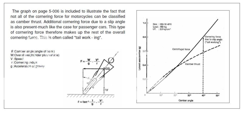


MT is steered by leaning (camber angle). By introducing another axis in the steering, camber angle, which also creates camber thrust. it creates a different type of equation to determine the lateral forces applied to the tire thus any math done on the CT is invalid for a MT.
Load Ratings:
CT on designed for a specific amount of load rate. Since the CT can be put on any wheel on any corner of the vehicle the acceleration loads and braking loads are not as specific as to the tire and to its load rating capacity. Since MT are designed specifically for either the front or rear, the extra load rating of either the acceleration (for rear) or braking (for front) loads are taken into consideration. So the load ratings for motorcycle tire are a little different than a car tire. You should always consult the owner’s manual for the amount of load rating you need. The load rating is not just for the weight of the bike, it also includes the braking and acceleration forces. Now if we do some basic math on load ratings for those that say the CT designed to handle "allot more weight". An average car with a high GVWR of about 4000 lbs will be used in this example. The Goldwing was a GVWR of 1200 lbs (without the acceleration or braking load rating). Since all CT are not designed for a specific place on the vehicle the must be able to share the load equally thus giving the tire a maximum of 1000 lbs per tire. Since the MT is designed for a specific tire location, they are designed to handle a certain amount weight from the bike. The Goldwing (and most bikes) have a weight distribution of 40/60 (front/rear). So if we take the GVWR and multiply by 60% (.6) we find that the Goldwing MT can handle 720 lbs of dead weight. Again this DOES NOT take into considerations of the acceleration loading on the rear tire. So the CT can handle only 280 extra lbs of dead weight versus the MT.
Tread designs:
Race tracks are pieces of exceptionally well maintained pothole-free road surfaces, with special crews that clean up oil spills and wipe off rain water with squeegies -- and thus tires for racing use often do not have any tread design at all or one with minimum treading (to maximize the rubber-to-ground interface).
By comparison, a modern street tire has to deal with a long list of possible road-surface contaminants and irregularities, including water (rain, snow, slush), oil, automatic transmission fluid (ATF), spilled diesel fuel, sand, dirt, soil, gravel, loose asphalt, ridged concrete, slab-gaps and expansion-fills, bumps, pits, potholes, reflectors, cracks (and grass growing from the cracks), tar patches, etc. The list is almost endless. To help compensate for these irregularities, the carcass design of street/touring tires are different from those of track tires, including the inclusion of tire treads (in the USA, DOT-mandated). Please note that not all treads are designed equal!
In the tire industry, the grooves cut or formed in tires are called "sea" and the ridges that border the grooves and the raised sections between the grooves are called "land". Different manufacturers have different land and sea designs, and even vary the land-sea design between tires in their own line-ups based on the intended use. Note that some designs have specific advantages over others.
For example, if the front tire has grooves that go around the very center of the tire for it's entire circumference (center line groove/grooves), then the tire's center-line groove's sea area will have a tendency to track concrete that has ridges running in the same direction as traffic, or the metal grating on open-grated bridges (like some draw bridges) -- and can induce a very severe front end wobble as a result, which is disconcerting to say the least. To avoid this, many manufacturers redesigned the center line to go back and forth across the tire slightly (an oscillating center line design), while others avoid a centerline groove all together. On the other hand, centerline grooves provide a benefit when riding in heavy rains, slush and slurry, as they help maintain road contact. It's a trade-off, depending on where you live and what kinds of roads you tend to face.
Similarly, tires designed specifically for off-road use will have tread designs with wide seas and very large land-to-sea height differences to compact loose soil and sand under the tire to maximize traction on that kind of surface. Enduro tires, which are designed to be used on packed dirt roads and other semi-improved surfaces will have yet another design over those of conventional street tires, designed to increase the foot-print of the tire to the road to help offset slippage.
Construction:
The design and construction of the carcass determine, to a great extent, the characteristics of the tire. Among the various design parameters, the geometric dispositions of layers of rubber-coated cords (plies), particularly their directions, play a significant role in the behavior of the tire. The direction of the cords is usually defined by the crown angle, which is the angle between the cord and the circumferential center line of the tire. As shown here.

When the cords have a low crown angle, the tire will have good cornering characteristics, but a harsh ride. On the other hand, if the cords are at right angle to the centerline of the tread, the tire will be capable of providing a comfortable ride, but poor handling performance.
A compromise is adopted in a bias-ply tire, in which the cords extend diagonally across the carcass from bead to bead with a crown angle of approximately 40*. A bias-ply tire has two plies (for light-load tires) or more (up to 20 plies for heavy-load tires). The cords in adjacent plies run in opposite directions. Thus, the cords overlap in a diamond-shaped (criss-cross) pattern. In operation, the diagonal plies flex and rub, thus elongating the diamond-shaped elements and the rubber-filler. This flexing action produces a wiping motion between the tread and the road, which is one of the main causes of tire wear and high rolling resistance. Generally there at least 6 plies but that depends on the tire manufacturer. With plies running from bead to bead and being more plies, it makes for stiff sidewalls.
The radial-ply tire, on the other hand, is constructed very differently from the bias-ply tire. It was first introduced by Michelin in 1948 and has now become dominant for passenger cars and trucks and increasingly for heavy-duty earth-moving machinery. However, the bias-ply tire is still in use in particular fields, such as cycles, motorcycles, agricultural machinery, and some military equipment. The radial-ply tire has one or more layers of cords in the carcass extending radially from bead to bead, resulting in a crown angle of 90*. A belt of several layers of cords of high modulus of elasticity (usually steel or other high-strength materials) is fitted under the tread. The cords in the belt are laid at a low crown angle of approximately 20*. The belt is essential to the proper functioning of the radial-ply tire. Without it, a radial-ply carcass can become unstable since the tire periphery may develop into a series of buckles due to the irregularities in cord spacing when inflated. For passenger car tires, usually there are two radial plies in the carcass made of synthetic material, such as rayon or polyester, and two plies of steel cords and two plies of cords made of synthetic material, such as nylon, in the belt. For the radial-ply tire, flexing of the carcass involves very little relative movement of the cords forming the belt. In the absence of a wiping motion between the tire and the road, the power dissipation of the radial-ply tire could be as low as 60% of that of the bias-ply tire under similar conditions, and the life of the radial-ply tire could be as long as twice that of the equivalent bias-ply tire. For a radial-ply tire, there is a relatively uniform ground pressure over the entire contact area. In contrast, the ground pressure for a bias-ply tire varies greatly from point to point as tread elements passing through the contact area undergo complex localized wiping motion. Note: that MT that is of the radial design has 4-6 plies run from bead to bead to give a stiffer sidewall that a MT requires. Most CT nowadays are of the radial ply design while most MT are still of the bias ply design.
Tire Beads.
We need to discus some terminology first. The terminology used for defining tire cords comes from the textile industry. Here is some of the common vocabulary.

Length and direction of lay
The sequence in both the length and direction follows the manufacturing sequence. For example:
3 + 9 + 15x0.22 + 0.15 5/10/16/3.5 SSZS
5S: lay length and direction of strand 3x0.22
10S: lay length and direction of strand 9x0.22
16Z: lay length and direction of strand 15z0.22
3.5S lay length and direction of wrap.
Product type
Several types of cord products are available based on variations in the manufacturing and twisting procedures. Regular cord – standard cord production in which the lay direction in the strands is opposite to the lay direction in closing the cord. This product is easy to produce, cost effective, and processes well in the tire factory.
Lang’s lay cord (LL) – cord in which the lay direction of the strands is the same as the lay direction in closing the cord. High elongation cord (HE) is a Lang’s lay cord in which the strands are loosely associated and moveable with respect to each other. This allows the cord to be stretched substantially and gives useful cut protection when used in the top belt of radial truck tires and impact resistance in the rock penetration zone of earth mover and mine tires.
Open cord (OC) - A cord in which the filaments are loosely associated and moveable relative to each other. This permits rubber to penetrate into the cord to maximize adhesion to the filaments and to prevent moisture wicking along the cord that could result in steel corrosion. This cord is difficult to process with standard calendering equipment as excessive tension during processing can close the cord resulting in void formation along the cord. Open construction cord has been the subject of numerous patents for various production techniques and cord designs. Bekaert offers a BETRU™ cord which is less sensitive to calender tensions and cord wicking.
Compact cord (CC) – cords are produced in a single compact bundle in which the filaments have mainly linear contact with each other. This construction is useful in applications such as for the carcasses of heavy-duty radial tires where severe fretting fatigue can occur at crossover points in a standard cord.
Tire cords are built up from yarns which in turn come from filaments. Filaments from a production spinerette are gathered together, slightly twisted, and placed on “beams” for further processing. A common hemp rope shows this construction, but on a larger scale.

The filaments are twisted “Z” into yarns and the yarns are back-twisted “S” to form a cord. The size of a tire filament, yarn, or cord is measured by its weight per unit length - linear density or “denier” (denier is the weight in grams of 9000 meters) or “decitex” (weight in grams of 10,000 meters). Textile cords are identified by their yarn denier and their construction. Thus a 940/2 8x8 nylon cord is formed from 2 - 940 decitex yarns twisted separately at 8 turns per inch and then back-twisted together at 8 turns per inch to form the cord. A 1650/3 10x10 rayon cord would comprise 3-1650 denier yarns twisted at 10 turns per inch separately and back-twisted together at 10 tpi. For a given material, use of higher denier yarns or more yarns per cord result in a higher breaking strength of the cord.
Here is a lists representative of constructions and properties of some steel cords used in various radial tires. Notice the breaking load value, cord diameter and the lay direction of the bead used in a motorcycle tire versus those used in a light truck and passenger car tire:
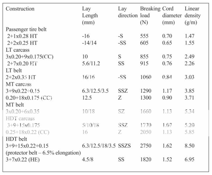
Steel bead wire is not considered a cord since it is not constructed from twisted filaments. In terms of steel cord nomenclature, a bead wire would be considered a filament. Tire beads are made from single steel wires of larger diameter. They are manufactured by several processes, including tape-wound beads, single-wire wrapped beads, or cable beads. Each type has certain performance or cost advantages. A similar wire is used in all of these constructions. The wire diameter, number of wires (or turns), and type of steel will depend on the size and load carrying requirements of the tire. Beads are designed with an over-pressure blow-off safety factor, load distortion resistance, rim slippage resistance, and resistance to bead breakage during mounting. Wires for beads are supplied as regular or high strength steel, in various diameters, and bronze or brass coated for adhesion. This table lists the typical properties of some standard bead wires.
Steel cord adhesion
For maximum long-term durability the steel cord used in radial tires must have a high level of rubber-to-brass adhesion and a high degree of resistance to corrosion caused by water entering the tire through road cuts and penetrating to the belt cord. Poor performance in either area can result in reduced tire service life. Thus, prevention of loss in adhesion in steel-belted radial tires is a prime consideration for tire engineers. The exact mechanism of brass-to-rubber adhesion has been the subject of much study and conjecture. Basically, it is conjectured that a bond is formed between the polar metals and the non-polar rubber during vulcanization with sulfur by formation of a Cu-S- Rubber bond, as idealized in this chart.
However, this bond can readily be converted to CuS with loss of adhesion under some circumstances. There are also indications that optimum bonding involves interfacial layers of oxides and sulfides of both copper and zinc. Bond durability is tested by measuring bond strength after various aging times and under various conditions: Dry heat aging, steam aging, aging in high humidity, and salt bath immersion. The rubber coverage of the wire after testing is regarded as equally important as the retained bond strength of the rubber compound. Corrosion (rust) of steel can destroy both the adhesive bond and the wire itself. Cord construction, brass composition, brass plating thickness, rubber compound composition, tire curing and storage conditions can all affect wire adhesion. This table summarizes the best choice of these parameters.
Each tire manufacturer adopts specific belt coat compounds. Many generic versions may be found in the literature.
Chemical Make-Up of the Tire
Motorcycle tires were originally built out of pure vulcanized natural rubber. The industry has come a long, long way since then, and have added various bits of chemistry into their tires to change the characteristics of the tires. Exact tire compound formulations are now closely guarded trade secrets for the most part, but that doesn't mean that we can't look at the basic compounds and explain how they change the tires.
The first compound is always the rubber base-compound everything else is added to, and these days it's usually synthetic rubber (which is consistant in it's strength and uniform in it's purity). Some manufacturers still add a small percentage of real rubber to their tires (usually for cost-effectiveness reasons), and a couple actually use significant amounts of natural rubber (the cheapest tires on the market).
After that, there are two other major chemical compounds in use: carbon black and silica. Carbon black gives the compound it's black color and it's strength, while silica improves grip under all conditions (but especially wet ones). Then come the minor chemicals -- anywhere from 8 to 45 of them, including cobalt salts, various artificial resins (both designed to improve adhesion of various layers to each other), anti-oxidants (to improve the shelf-life of the tire), plus various other chemical compounds to improve different aspects of the tires. Most manufacturers pre-mix their rubber compounds before they hit the tire forms, but some of the newest motorcycle tire forming systems actually compose the chemicals on the spot at the tire forming machines.
Now, let's go back to those two major chemical additives (carbon black and silica). By varying the percentages of these two chemicals in the formation of the tire's compounds, manufacturers can vary the hardness or softness of the tire, as well as the tackiness or grippiness of the tire. Replacing most the carbon black with silica reduces the hardness of the tire but promotes strength between the rubber molecules at the same time (and silica runs cooler than carbon black). But, removing most of the carbon black also reduces the lifespan of the tire, and may prompt the tire manufacturer to make a thicker tire to offset the removal of carbon black. Track tires are traditionally high in silica and low in carbon black compared to street tires, because grip is of paramount importance in track environments (and lifespan isn't, since most races are limited to 80 to 150 miles in length).
Lately, a number of manufacturers have also been varying the initial bead size of these particles to improve the evenness of the mixture. Most tire manufacturing processes start with the raw mixtures preformed as small beads which will be joined in a heated press to form the tire layers in the press. R&D at these firms have found that they get new material matrix formulations by stepping to a smaller bead size, which can provide benefits in seeming contradictory values -- both better grip and longer life than prior generations of tires that used the same chemical basis in a larger bead size.
Car Tire Designs
All CT manufactures only allow 40 psi to seat the bead. Any more and it begins to stress the all components of the tire. Excessive air pressure can lead to catastrophic bead failure. It may not happen at the time of the install but could happen later due to stress on the bead. The car tire's tread area is generally designed to be flat. Some tires do have a slightly rounded edge at the shoulder. Car tire are designed for a maximum of 4 degree camber (lean) any more than that and the sidewall is designed to flex and try to get the tread to lay flat on the road surface. This is a bias ply versus a radial tire to show how the sidewalls are designed to flex to keep the tread in contact with the road surface.

As the sidewall flex's it tries to make the tire stand straight up. This is why, by even darksiders own admissions, they must continue to counter steer the bike while in a corner. Once the CT gets to 10 degree of camber it has lost half of its contact patch. At 20 degrees of camber the tire has started to ride on the shoulder and is running on about on third of the contact patch. At 30 degrees of camber the tire is riding on nothing but the shoulder. At 40 degrees of camber the tire is starting to ride on the sidewall. As seen here:

The more the tire runs on its edge or shoulder the faster it heats up as seen in this Hankook tire test:

Please note the above picture is a car tire running in its normal operation with less than 10* of camber. As you can see the cross hairs of where the load is being placed is running close to the shoulder of the tire and
how hot the shoulder of the tire is getting.
The wider and the less of a profile a CT is the more dependent it is on the correct camber. On Ct the tire compound is the same across the entire width of the tread. All tires regardless if they are CT or MT are designed to operate at a certain temperature to have maximum grip. Car tires generally run at a cooler temperature than motorcycle tires. If a tire runs too cool, it loses its ability to grip the road surface and conversely if a tire runs too hot it can delaminate. The rolling resistance co efficiency will affect the tire temperature. If the tire is operating correctly the air pressure will rise 4-5 degrees when hot. On most CT laminations they use what is called a butt joint when the carcass meets up it will look like this __][__. This again is done because the tire is uni-directional must be able to rotate any direction.
Motorcycle Tire Designs:
Motorcycle tires are designed with a round tread area. With the round tread profile, once you counter steer the bike into a corner, it will stay leaned over in the corner till either you lean more or pull it out of the lean. Once the bike is leaned over in the corner, it is the rear tire that actually steers the bike. The smaller the radius on the tread the faster the tire will respond in corners. The wider the profile the more stable it is in straight up riding and slower it is to respond in corners. Some tire manufactures have done what is called a variable radius profile. The radius will get smaller the more you get towards the sidewall thus creating a fast handling tire but stable at straight up riding. The compound on MT is very different than that of a CT. Most MT have 3 segments, some have more (racing tires). The first segment will be equal widths on both sides of the crown. This segment has a hard compound for straight up right so to give long wear life. There are two more segments that flank to each side of the center segment. These segments have a softer compound to get more grip in the corner. The lamination on all MT is what is called a feather edge. The edge can over lap any where from an inch to several inches thus the carcass will look like this with varying amount of overlap. __//__ This again is why there is a directional arrow on the sidewall. The tire manufacturer does not want the leading edge of the overlapped carcass going first. It will quite literally try to rip itself apart while cornering. MT need a 100 mile break in period. Most tires will expand in width by about 3-8% because of the heat cycles.
Traction:
First we have to understand the laws of friction to understand traction.
The first law is easy to believe: The friction between two surfaces is proportional to the force pressing one to the other. This force could be the weight of a motorcycle pressing the tire into the pavement, or the clamping force pressing two pieces of wood together. "Proportional" just means that if you double the pressing force you double the friction.
The second law is where all the trouble starts. To understand it, suppose you set up an experiment. You put a brick on a table and investigate how much force it takes to start the brick sliding. You screw an eyebolt into the brick, run a line from the eyebolt to a pulley on the edge of the table, and then attach weights to the end of the line. You add weight until the brick starts to slide.
Now here's the interesting part, and the surprising part. You would notice that the orientation of the brick doesn't make any difference. That is, the friction is the same whether the brick is on its large face, the smaller side, or the small end.
The friction is independent of the contact area.
Don't believe it? You're not alone. Bowden and Tabor, in their book Friction, tell about one of the first modern investigators of friction, Guillaume Amontons. In 1699 Amontons published a paper on friction in which he reported on the two laws. As Bowden and Tabor put it, "The second law, that friction is independent of the size of the bodies, was viewed by the [French Royal Academy of Sciences] with astonishment and skepticism. They instructed their senior academician De la Hire (1640-1718) to repeat Amontons' experiments and check their validity. This he did and confirmed Amontons' conclusions. Amontons' laws of friction have remained with us to this day as a very good working approximation."
It'd probably be less counterintuitive if we could see the microscopic texture of surfaces. Imagine a flat perfectly smooth metal plate. It's flat and perfectly smooth, right? If you think so, you've never seen a micrograph of a flat perfectly smooth plate. It's actually scratched and pitted, like a mountain range in the small.
Now imagine a couple of mountain ranges on plates. Turn one over and put it onto the other. The actual contacts will be parts of the various peaks of the two plates onto whatever part of the other plate happens to match the peak. Those peaks — asperities (how well the two flow together), the tribologists call them — are where the friction occurs, not, obviously, in the valleys where there is no contact. Press them harder and you'd get more actual contact as the asperities bend under the pressure.
If you take another pair of mountain ranges/plates of twice the area and pressed them together with the same pressure, the actual contact area of asperities wouldn't change. You'd have the same number of asperities in contact, but further apart, in the larger plates. Only additional pressure would change the true contact area.
That, in a nutshell, is the model that people use to make sense of the experimental fact that F=μN: friction F is proportional to the force N pressing two surfaces together, with proportionality constant μ. (Apparent) area of contact does not enter into it.
To try to help explain asperities better I am going to give some real world examples.
If you have a car with 6” wide tires on a sheet of ice 1” thick and tried to go you would just spin the tires. If we use the theory “wider tire means more contact patch which gives us better traction” we should be able to go if we increase our contact patch from 6” to 8”. So we change out from 6” to 8” tires and w get the same result. We would get the same result even if we double it to 12” wide tires. Why? F=μN F=traction, μ=grip and N=force applied. We have not changed anything in our equation. If we add ½” long spikes to the tires to increase the μ or asperities, or how well the two flow together, we now can move the car on the sheet of ice. The longer the spikes the better they flow into the ice thus increasing our μ or grip. The more we increase the grip the faster the softer of the two components will wear out.
Sometimes people object that the above model may be satisfactory for rigid materials like metals, but rubber would flow into the valleys and you'd get better contact. They miss the fact that rubber at the microscopic scale is quite as irregular as metals are. Pressing rubber onto an irregular surface such as pavement will indeed result in greater area of actual contact (as opposed to the apparent macroscopic area) than might be the case with a metal on pavement, but that contact is still between irregular surfaces; there will still be plenty of gaps in contact. Reducing the gaps can be achieved by pressing harder, which will result in more friction — just as the equation F=μN predicts.
That's the model, anyway. How well does it match the reality of rubber friction? A careful reading of Robert Horigan Smith's book Analyzing Friction in the Design of Rubber Products and Their Paired Surfaces (2008, CRC Press) appears to indicate that rubber friction has more components than the single one of adhesion, which is what F=μN models, but that any departures from that model are minor and lost in the noise of real-world tires and pavement. Smith analyzes the published literature of rubber friction and concludes that rubber friction arises from 4 sources. One is due to the wear of the rubber, which is undetectable in non-sliding situations such as tires rolling on pavement. Two others he calls microhysteresis and macrohysteresis, which arise from the not-quite-elastic deformation of the rubber. They are very minor in comparison to the fourth source, adhesive friction, just what is modeled by the above two classical laws of friction.
Smith argues that engineers concerned with rubber friction — tires, shoes, automotive fan belts — who neglect the hysteresis forces are missing a significant design tool. But by far the dominant contributor to tire friction is adhesion, which is well-described, by the two classical laws of friction: It's proportional to the force pressing the rubber to the road, and independent of apparent contact area.
With this information and no more, we can understand two important facets of motorcycle operation. The first law, that friction (which we call traction in the context of tires on road) increases as weight increases, explains why the front brake on a motorcycle (and a car for that matter) is so much more effective than the rear brake. As you slow a vehicle, the weight transfers to the front. We all recognize this; it's why the bag of groceries on the seat slides onto the floor when you get hard on the brakes. So the front tire is now carrying more load than it was; thus it now has more traction than it did. The opposite is happening at the rear: The rear tire is now lighter than it was, and so has less traction. The harder you brake the more the weight and hence the traction transfers forward.
Everyone knows that you have less traction in a lean than when the motorcycle is straight up and down. This is because, in a lean, there's less rubber on the road.
Right? Well, if you've been paying attention, you'll realize that what everyone knows, is wrong. The second law says that friction is independent of contact area. That implies that, if the traction is indeed less, it isn't because there's less rubber on the road. The second law says that the amount of rubber on the road is not relevant. (It's interesting to me that people who know what everyone knows always overlook the fact that there isn't less rubber on the road in a lean. Motorcycle tires are round. The amount of rubber on the road is the same whether the motorcycle is straight up and down or leaned over.)
So what everyone knows about why there's less traction in a lean, is wrong. Maybe everyone is wrong about the reduced traction as well? They are. The first law says that the friction between two surfaces is dependent only on the force pressing them together; in our application, that's the weight of the motorcycle. Does the motorcycle weigh less in a lean than straight up and down? Of course not; if that were true, we could lose weight simply by leaning over.
Ok, so we've concluded that the amount of traction in a lean is exactly the same as when straight. So what's the origin of this myth? It's certainly true that if I'm leaned far over and apply much braking I'll lose traction and slide. What's the deal, if there's just as much traction in a lean as straight? The explanation is that one's available traction has to be shared between the various users of traction. The Motorcycle Safety Foundation has a good image in their experienced rider course book. The total traction available is represented as an oval or circle, and the things which use traction are partitioned in it.

So with this in mind, it's not hard to understand why we can't brake hard while in a lean. When cornering hard, most of our traction is being used for turning, with some for acceleration, and little or none for braking. The diagram looks like this:

The size of the circle is the same because we have the same amount of traction as we did while straight, just as the first law requires. Much of our traction is used in cornering. There's some used in accelerating, if we're on the gas through the curve. Drag at the wheels is always present so I've represented a small amount of traction for that. So what's left over, the white "reserve" sliver, represents all the traction that we have to work with for any emergency, such as braking for an unexpected obstacle or because we went into the corner too fast. It is the small size of the reserve which gives rise to the myth that traction is lacking in curves. Or, if you prefer, it isn't a myth, merely worded differently. The traction which one has to work with in curves is much smaller than that available in a straight line.
So if traction doesn't depend on amount of rubber, how come high-performance tires are so large? Huh?
To understand this, we have to make the first law more precise. The friction between two surfaces is proportional to the force pressing them together. But the friction between these two surfaces can be quite different from the friction between these other two surfaces, even if the force on them is the same. It's easier to slide a steel plate on pavement than a rubber tire on pavement, even when both are loaded with, say, 5 pounds.
The two laws can be combined into a single equation: F = μW, where F is the friction between two given surfaces, W is the force pressing them together (the weight, in most of our examples), and μ (the Greek letter mu) is a number called the coefficient of friction. This equation says that the friction is a percentage of the total weight on two surfaces, the percentage being given by the coefficient of friction. (That's really just the first law, saying that the friction is proportional to the weight, the constant of proportionality being given by μ (grip). The second law is incorporated by the fact that the area of contact does not appear in the equation.)
The fact that some surfaces are "stickier" than others is reflected in the different coefficients of friction. Steel on pavement has a much lower value of μ than rubber on pavement. And what's more, different rubber compounds have different values of μ (grip). You want more traction? Just use stickier rubber in your tires. A further complication is that the coefficient of friction varies with various physical parameters. For instance, cold rubber is harder and thus less sticky than warm rubber; the same equation applies but μ is lower for the cold rubber. Static friction, the force necessary to start sliding, is greater than the friction created while sliding. In riding, we're concerned with rolling friction, which is somewhere between static and sliding friction. Again, same equation, but three different values of μ.
If you switch to tires with a better coefficient of friction, you'll immediately notice that stickier rubber is also softer; it wears out much more quickly. Motorcyclists accept the need to replace high-performance tires more often than touring-oriented rubber, but the auto types have another option: They can use wider tires to spread the wear over more rubber. And there, finally, is the reason high-performance auto tires are wider. It isn't to get better traction. Better traction comes from stickier rubber. The tires are wider to get acceptable wear from the stickier, softer rubber. (As well as for other things like heat management, rigidity under the stresses of cornering and braking and acceleration, etc.)
Continued on next post.....


 opcorn: