Steve Saunders Goldwing Forums banner
181 - 200 of 543 Posts
Looked at the Megasquirt family first, then was introduced to the Speeduino. Speeduino tickled my fancy.

Have considered sequential fuel injection but since this is my first foray into the ECU world, I'll focus on getting what I have and how it was designed working well, then move forward with more advanced features.

Believe the 1500 came standard with a 12-1 trigger wheel sandwiched between the timing belt crank pulleys. Megasquirt can use this. Looking for one of these up here as a back up. Thinking that a 36-1 would be a bit overkill for my application.

My 1200 has the cam sensors (2 in number - Gr/Gl) out the back of the right side cylinder head, will be using one cam sensor in conjunction with the 8 tooth crank sensor. These cam sensors are Hall effect and put out an analogue signal. Have an old Gr/Gl sensor set that I will not be using. If you would like it, PM me your address and I'll post it. It'd be like the space shuttle program. Canada's contribution was the space arm, key component to each mission. If you used the sensor, I'd feel like I contributed - LOL!!
The 1200 and 1500 crank sensors are VR sensors and other than the size, can be used interchangeably. The PG sensor harness from the '85 to '87 Aspencade work well for a crank sensor, have this installed on my 1200 engine.

Have ordered the 14point7 Spartan 3/Lite with an LSU ADV sensor - not inexpensive at $159.00 USD. Have to drill a hole for the bung, not a lot of choice as to where.

I lose a couple of features such as the OEM ECU diagnostics - thinking about a piggyback unit that emulates this function, and the dash ECU indicator warning light. Should have everything else the same.

Cheers
 
Discussion starter · #182 ·
These cam sensors are Hall effect and put out an analogue signal. Have an old Gr/Gl sensor set that I will not be using. If you would like it, PM me your address and I'll post it. It'd be like the space shuttle program. Canada's contribution was the space arm, key component to each mission. If you used the sensor, I'd feel like I contributed - LOL!!
Haha - wicked :) Thanks so much for the offer. I had missed this message though and between the time you had posted it up and now I have already cobbled together a Hall sensor setup.

Interestingly I did not realise the 1200s had hall sensors fitted. I knew some were injected but I had never looked into the setup. I'd love to see the setup and how the cam sensor fits in place. I did wonder about fitting my cam angle sensor at the back but I wasnt sure about how best I could have affixed a suitable 'tooth' or whatnot to the end of the camshaft that the sensor would register.

Cheers

Alex

now its update time so you can see my efforts in homemade efi stuff :)
 
Discussion starter · #183 ·
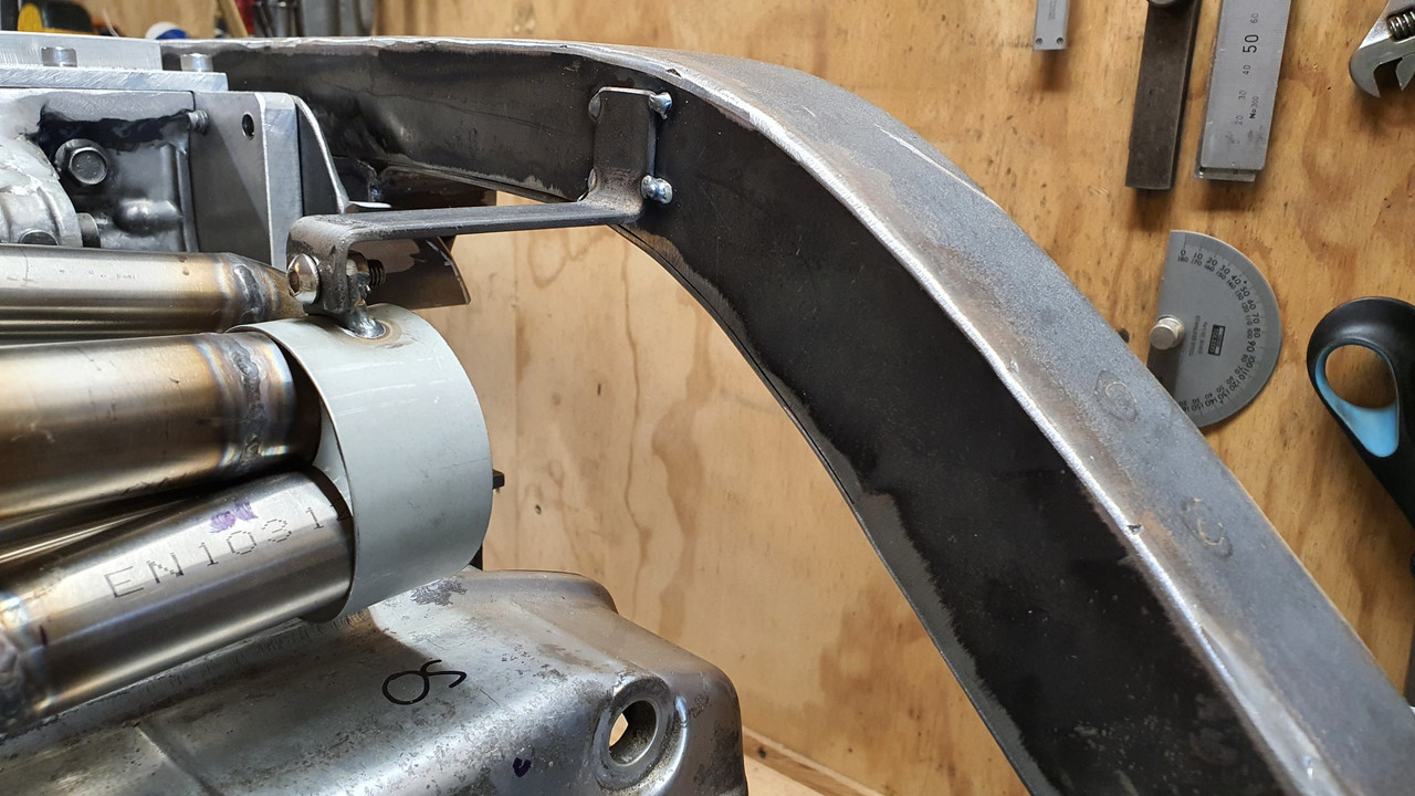
nlet fun over and time to move on to some other jobs. First off was to start on the pipework for the cooling. Like I mentioned a while back the heads are symmetrical and each has a outlet for the hot coolant. So one ends up at the front and one at the back.

Here's the back one...


Both just visible in this shot...


On the bike these were plumbed so they joined up near the middle and went into a thermostat housing and from there to the radiator. But I will be running an electric pump behind the engine so that's where these outlets have to be plumbed towards. I started on the front outlet. I gathered together the bits of pipework from the bike setup..


I chopped them up and using bits and pieces I welded together a pipe for the front. They are very thin- about 1mm so it was a tricky one for my tig skills but I did ok. I'll probably paint them and that'll hide the lumps
:)


Pipe went like this...


Holes = whoops..


Bracket..


And that was all I could do for now as I had used up what bits of the old bends I could. I have ordered some 22mm bends from Aliexpress and so I wait.

Better start sussing out the injection gubbins then. I went into the store room and dug out the box labelled 'electronics' and another full of various sensors I'd been collecting. Blew the dust off them and sort of like xmas day I carefully removed all the goodies within. Laid them out on the work table and this is what I had...


The brains of it all is a second hand Megasquirt 3 with the expansion board. Apart from the faster processor, SD card slot, loads more ins and outs, canbus etc etc it also allows for fully sequential injection. I'll need to change some of the jumper wiring because its setup for a stepper idle valve and a hall sensor on the crank but otherwise its all good.


I have a few VR and hall sensors to try out..


Temp sensors ...


First thing was to plug in my megastim and power it up then test the ecu out. Its all working fine. Its been ages since I have used tunerstudio. Not used it since I sold my Viva.

 
Discussion starter · #184 ·
Now time to start on setting up sensors to suit. Starting with the crank sensor. The Goldwing came fitted with a 12-1 trigger wheel and two VR sensors (called pulse generators in bike world) to run the ignition module...


I could have just kept the trigger wheel as is but for better resolution on a full engine management setup it makes sense to go for at least a 36-1 trigger wheel. I knew there would be nothing available even close to fitting my needs so I made one in much the same way as I did for the Viva.

I cut out a disc with the plasma cutter..


Cleaned it up in the lathe and drilled/machined out the bore, ensuring it was perfectly concentric to the bore. The VR sensor needs to have no more than about .020" clearance.


Made a jig for the drill and using the original trigger wheel I was able to mark out the teeth.


I set the jig up with a locator bolt so I was able to turn the wheel one tooth at a time and drill it and then repeat...


Then I carefully cut out up to the holes, gave it a tickle with a file and I had my trigger wheel. I have yet to remove the 'missing tooth' or tig in a nib in the centre that keys to the crankshaft. I'll sort that later.


Now I had to sort out my second sensor wheel, for the cam or 'home' signal. This will be a single tooth or maybe a half moon. I'm not sure and have yet to work out what's best. The MS manual suggests a half moon type (like one long tooth). Other OEM setups just have a single small tooth. Either way I need a sensor to be mounted near one of the cam pulleys.

What seems to be recommended as the better option for the home signal is a hall sensor due to the fact that the camshaft spins at half the speed of the crank and when the engine is being turned over at startup it could potentially be quite a low speed. So low that a VR sensor might not be able to produce enough of a pulse for the ECU.

I had played around with a couple of VR sensors out of interest to see if they might fit in place but everything I had was too bulky or the wrong shape to fit under the cambelt cover...


Anyway- they were VR sensors and not what I wanted. I looked about on googleworld and found a couple of hall sensors that looked like they might work.

Another trip to my local wreckers was called for. I rummaged about in various engine bays and found what I was after in a 2003 Peugeot 307. It was ideal! I grabbed the plug with a length of wire attached. Once home I whipped up a bracket from some thick walled alloy angle, a hacksaw and file and had the sensor fitting where I wanted it.


Once I have decided what type of toothed wheel shape to make I'll be sorting that out.

After all this I stripped the whole engine down and removed the crank...


The next day Hannah and I took the imp for a hoon and visited the big smoke, Nelson city, to do some shopping. I'm now sussing out where to get my crankshaft balanced up - without a doubt this is one job that has to be done.

Imp looked great against the blue sky along the promenade in Nelson
:)
...

 
Great work as always.

Here's a picture of the cam sensors on the back of the right side cylinder head. The cam shaft protrudes out the rear and the cam sensors are connected. Only using one cam sensor for the Speeduino. Using the dual wheel setup:


The magnets under the sensors are a bit of a mystery. The only sensors that require a magnet of such are Hall effect sensors. Lots of theories regarding this, but no definitive answer.
 
  • Like
Reactions: yoeddynz
Discussion starter · #187 ·
View attachment 330938 View attachment 330939

The magnets under the sensors are a bit of a mystery.
It looks like a simple half moon profile on that camshaft end. Similar to what I want to make for my pulley. The idea being it gives the ecu a much clearer simple 'on, off' pulse at low engine speeds like at start up.
Yeah I know what you mean about the info out there on sensors. There's a fair bit of it and it can be a bit muddy. Like you said - there's a few different hall sensor designs. Safest thing for me was to get one from a car, especially as some hall sensors available new from suppiers for electronic hobbies are often not able to cope with the heat when bolted to an engine.
Your lucky you already have a cam setup ! Like I said earlier- I never realised the injected 1200s had this :)

Awesome work, your skills never cease to impress me.
Thanks very much for the kind words. Glad I'm entertaining ya'll.
 
Great work as always.

Here's a picture of the cam sensors on the back of the right side cylinder head. The cam shaft protrudes out the rear and the cam sensors are connected. Only using one cam sensor for the Speeduino. Using the dual wheel setup:

View attachment 330938 View attachment 330939

The magnets under the sensors are a bit of a mystery. The only sensors that require a magnet of such are Hall effect sensors. Lots of theories regarding this, but no definitive answer.
Those are simple old school inductive sensors. Used long before solid state sensors became the norm. Really simple just a coil of wire, a magnet, and a moving hunk of iron.
 
Discussion starter · #193 ·
Slow progress is progress nonetheless. I have made the sensible decision not to stress out and try to get this engine swap in for oldschool nats. That was a big carrot to aim for but its not realistic now. There are far too many other jobs going on with our landscaping etc plus several family members are coming to stay over the next couple of months and we both want to enjoy some holiday time.

I think the main reason though is that I know how stressy its can be trying to rush a project and suddenly the fun has gone and corners start to get cut. If I take my time and work on it when I really want to then it'll be better for it.

All that aside- I have still been plugging away on it and today it rained all day so I had no excuse but to stay inside and finish off a long tedious, but satisfying, part of the conversion. The exhaust headers.

But before I delve into that part there's some other bits that have happened.

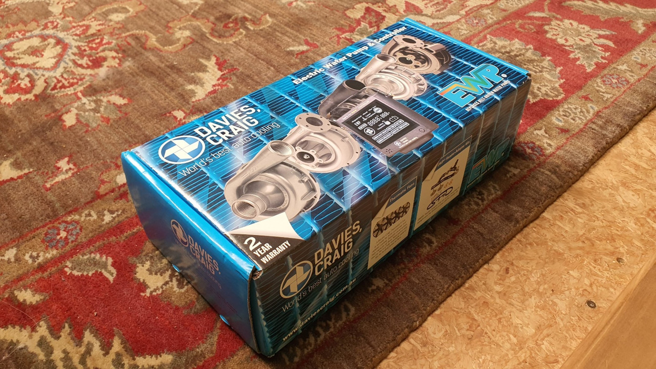
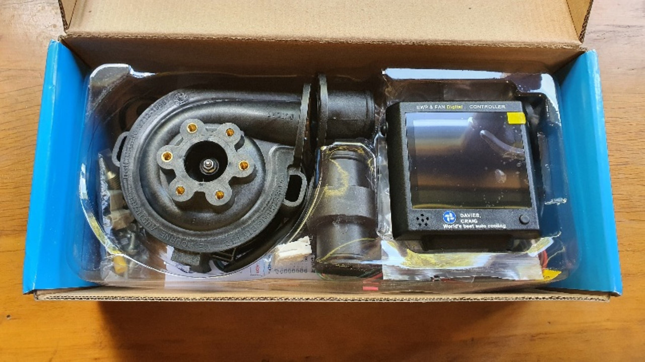
I blew the dust off my bank card and bought an spendy shiny part of the project.


Yay. I got it while they were still on sale and it can now sit in the store room to collect some dust.

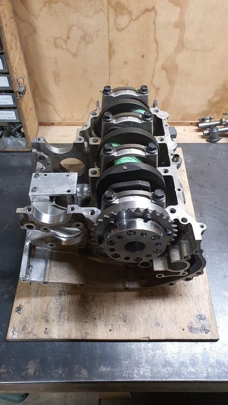
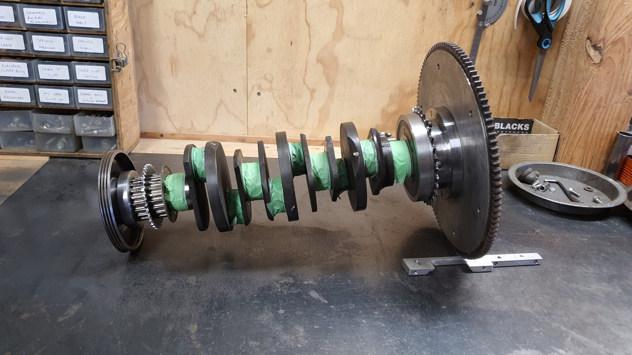
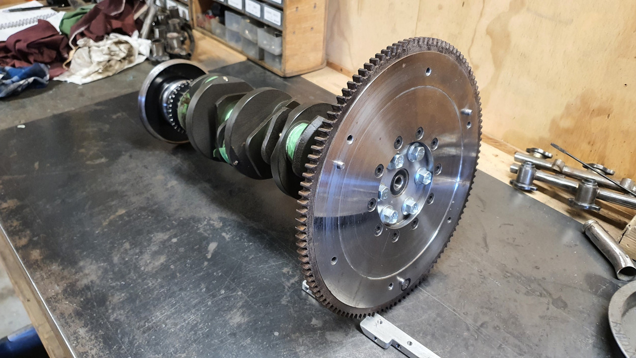
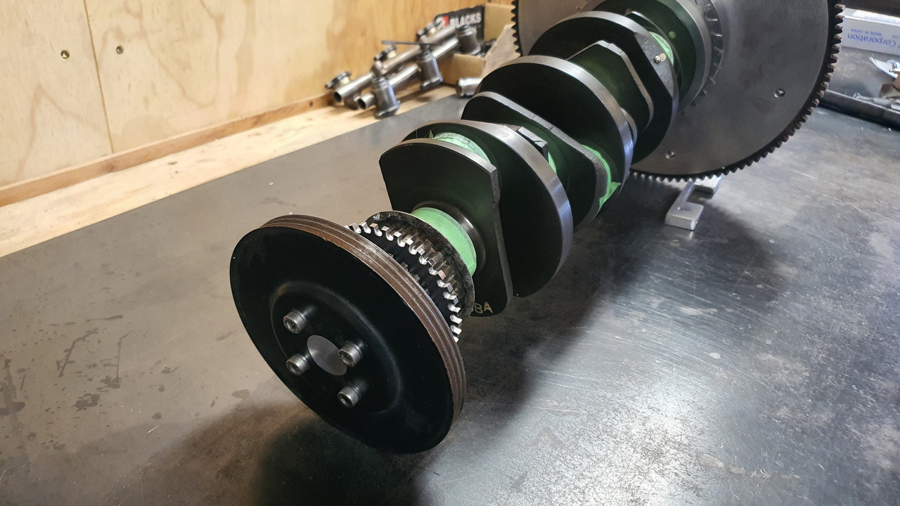
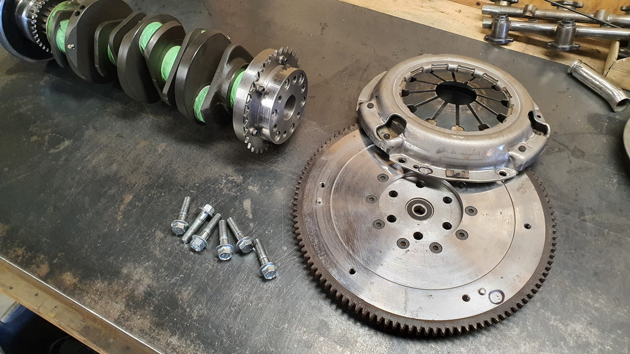
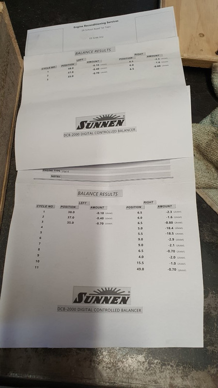
Another thing that I had to spend some money on, as mentioned in the last update, was to get this lot balanced..


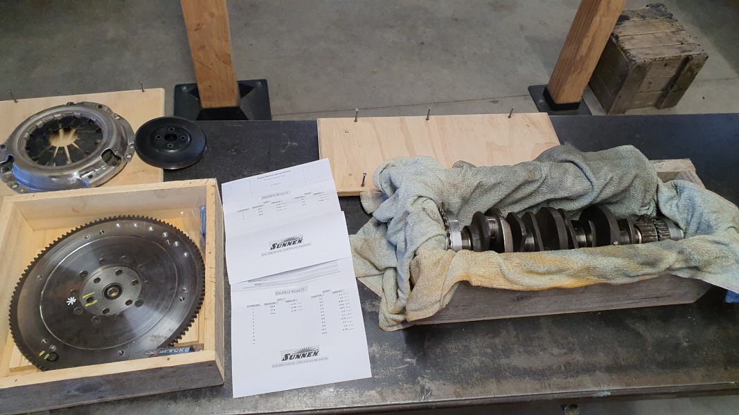
I made some inquiries about and found an outfit very well recommended by many down in Christchurch. The owner Evan was very helpful and managed to fit the job in to suit my brothers trip south - saving plenty on postage!

I whipped up some sturdy wooden boxes to suit and away they went.


A couple of weeks later my brother returned them to me with a properly balanced assembly.


They'll stay stashed away safe until I can assemble the crankcase- which really is just waiting on me to give the pistons a clean and make some custom ring compressors similar to the honda items for assembly of the two halves. More on that later.

Back to that exhaust thing. I looked at various options for how to go about making some headers with compact enough bends to suit. Kept coming back to getting some bends and piecing them together bit by bit. I decided that with the tighter bends I knew I'd end up with that I would go up one size, 28mm, on the header tube diameter to help keep the flow nice.

The maths works in my head so I'll go with it. Really all I need to do is get the hot stuff out of the heads and out the back.

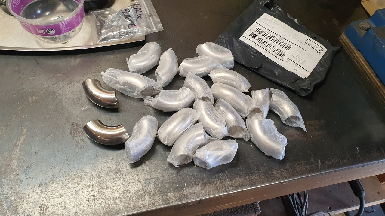
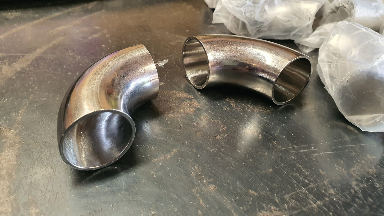
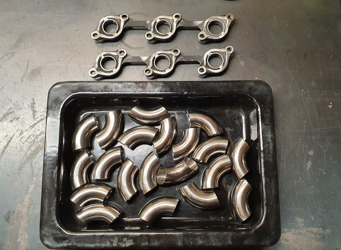
Priced up various bends within all the NZ suppliers I could find. Horrendous prices. Did an order through Ali express for a load of stainless bends of which arrived 10 days later - a nice surprise.


They'll do fine.


Plasma cut some flanges to suit a jig I was going to make - exactly like I did on my Viva V6.

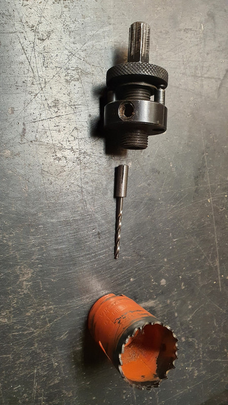
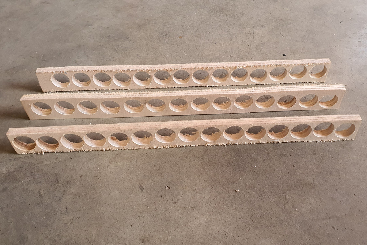
Machined a little sleeve so my holesaw would take a tiny drill bit.


Then I made lots of holes.


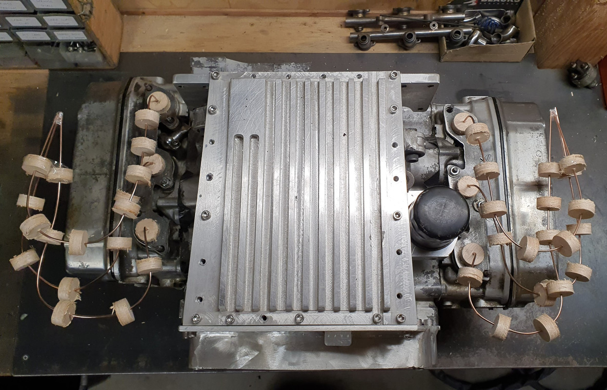
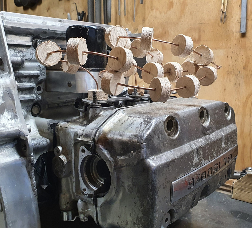
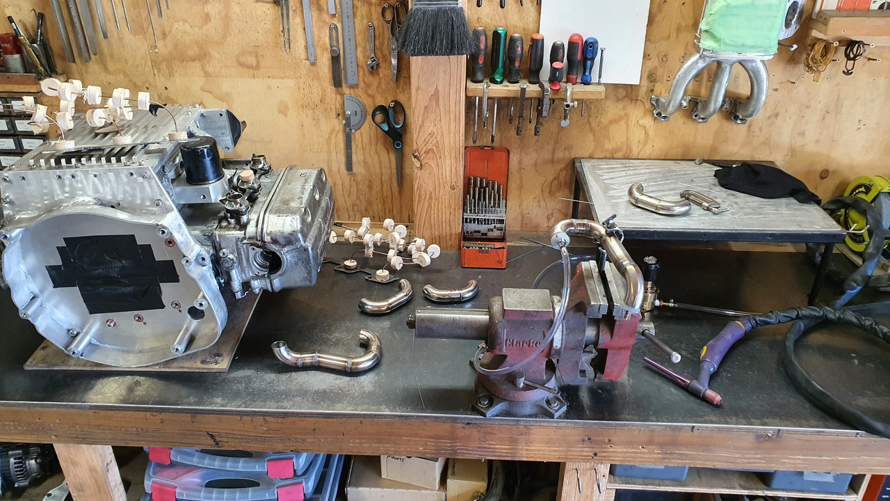
The bits that the holes gave up (wooden marshmellows) were pushed onto equal lengths of tig rod which had been welded to the centre of each exhaust outlet area on the flanges. I was then able to bend them to suit and mock up my exhaust header runs. From what I have read it was not strictly needed to try and match the primary lengths on a flat six as there is nothing really to be gained. But it cant hurt to keep them matched so that's what I did. I wanted them tucked up away with no chance they can get smacked on anything and made sure I could get to the oil filter easily.


Now I knew what I was going to build I had to copy them with this lot..


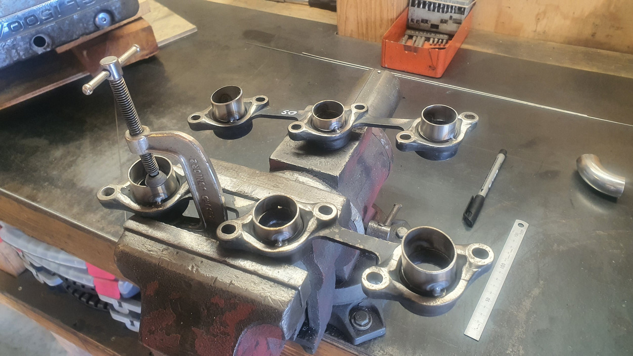
I cut the remaining stubs off the old header flanges and tacked in some short bits of stainless tube..


I started to tig them in but the steel on the flanges was really odd and did not tig weld at all nicely. The arc was all over the place. Maybe magnetic? What ever it was it had me stumped. I ended up mig welding them - heaps of weld which I then ground down with a flap disc.
 
Discussion starter · #194 ·
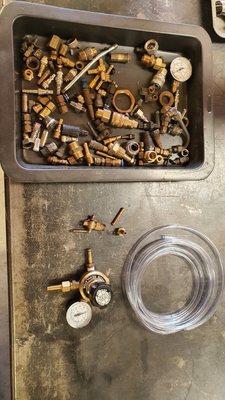
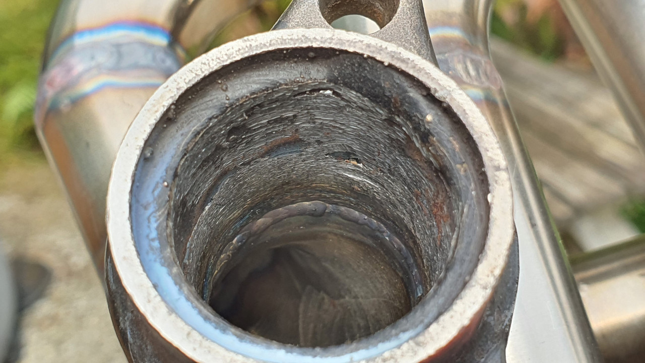
Now onto building the runners up. This is the first time I have made any headers from stainless steel and I wasn't going to take any chances with oxygen affecting the back of the welds ('sugaring') so leading to potential weakness or cracking. So I would have to purge the inside of the tubes with argon. I didn't have a suitable purging setup and buying the bits was a bit too spendy for my liking. Instead I rummaged through my box of old brass fittings...


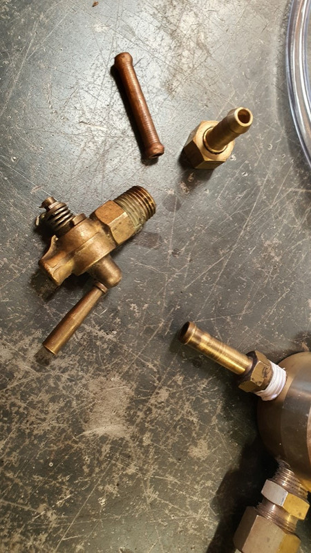
dug out an old argon regulator and removed one gauge. Bought some vinyl tube ($7 ...big spender) and cobbled together something..


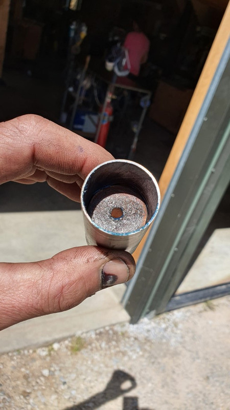
I needed something to plug the tube ends quickly and easily. I'd seen many people using tinfoil but it looked awkward and leak prone. I made a mold using a bit of tube the next size up, a bit of wood, a bit of copper tube and some grease.


Filled it with budget bathroom silicone sealant. out popped some plugs which I shaped to a taper in the lathe with a flap disc. Hey presto- heat resistant tube plugs...


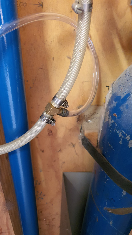
Tee'd a line off the main feed to the welder. It worked a treat. I'd set the main regulator on the bottle to flow a bit more and then set the extra reg to flow just enough. I would then set the actual flow rate through the tube using the little brass tap so I could just hear the gas flow through the tube..


I was very happy with the way the welds on the inside of the tubes stayed so smooth and clean. No yucky porous flaky crystalised welds.


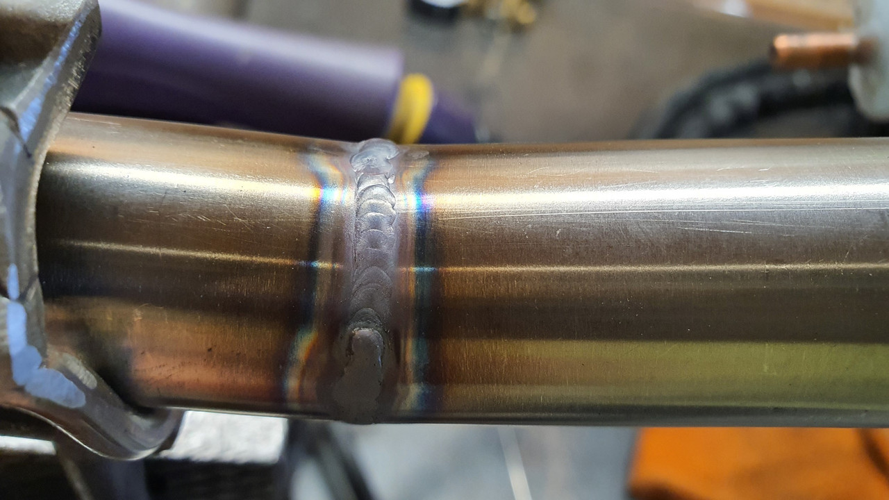
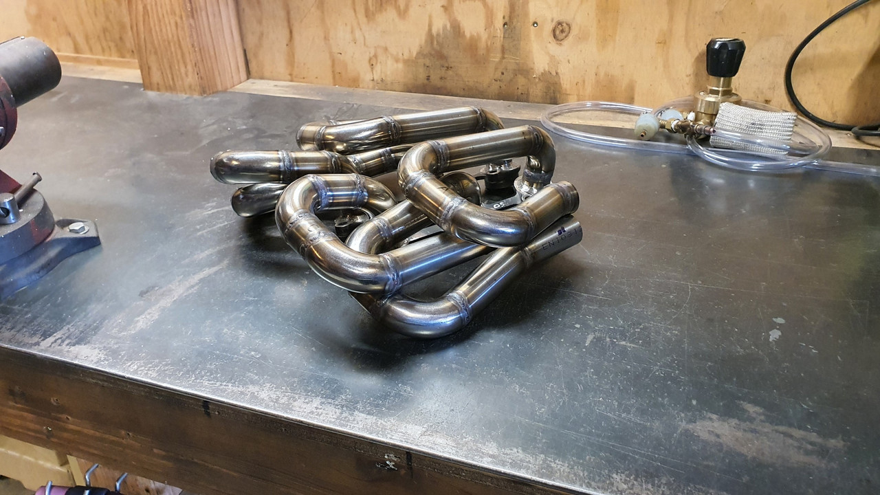
But there was nothing I could do about the appearance of my welds on the outside. I really can't make any excuses - I'm just not not experienced enough at welding stainless tube. So my welds here I shall call functional. I'm not even going to bother trying to clean them up. All I wanted was decent penetration and strength.

My welding did improve over the duration of building these. There were glimmers of neatness...


I had to use a foot pedal again- something I had stopped using years ago because its a hassle when building awkward furniture, kitchen framework jobs etc - which is the most common thing I use the DC for. I got used to the pedal again and started spotting where I was going wrong. Mainly my speed and feed technique required was too slow- (the tube I'd bought was 1.2mm - a bit thin perhaps but all I could find in this diameter). I bought a bigger shroud for my gas lens which helped too.

So yeah - I'm afraid there will be no welding porn with these headers. I will cunningly take my photos from a distance
:)


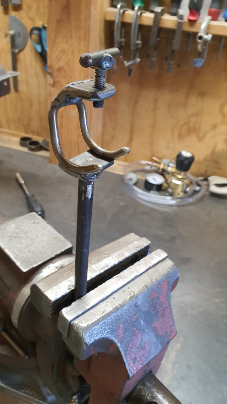
I got tired early on of trying to hold bits of tube awkwardly in the vise to weld them so I built this little tool..


and bits of wood turned down to locate tubes to bends for mocking purposes..


plus a jig on each side to build towards and make sure the ends align with where I wanted them to head..


things took shape and I enjoyed the process...


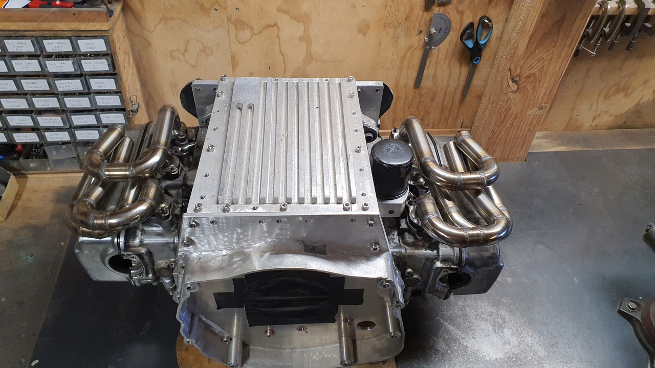
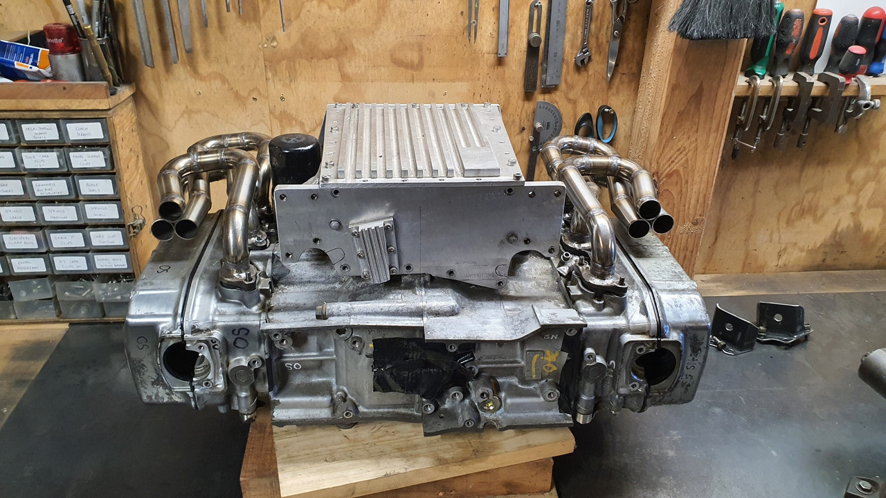
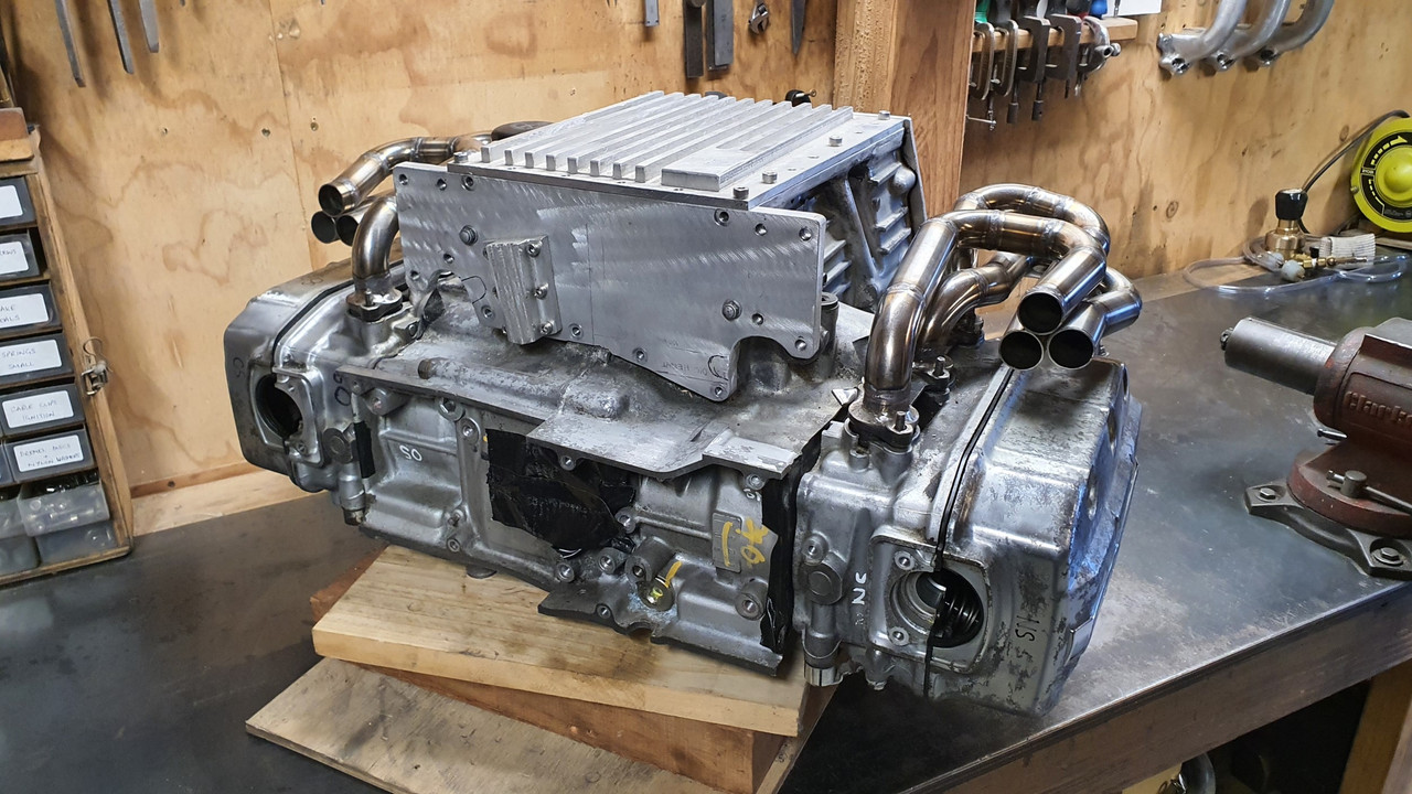
Finally today I finished the last bits. I will now have to make up a couple of reducers/collectors to suit. They will feed into a V band flange, then a flexy joint on each side, then straight back to a large silencer assembly mounted across the back, pretty much like an early 911 has.

For now though I'm just very happy to have some headers built that from a metre away look quite fancy
:)
...


They sit nicely on the engine. I'm not sure if I'll use any heat wrap as I have always done in the past - I'm a big fan of it (opens up a pub debate..) I'll have to see how they go.


Next thing to look at is finishing the water pipes. I'd also bought some smaller stainless bends for that but now realise I'd not bought enough. Ho hum.

Maybe I'll find some under the xmas tree (red and white striped)
 
Amazing. The thing is going to sound like a Porsche race car!
 
181 - 200 of 543 Posts