Steve Saunders Goldwing Forums banner
141 - 160 of 543 Posts
As I'm limited to the dimensions of the bike, I chose the 'easy' route of a 50bhp single shot nitrous system - 147bhp at the rear wheel. I do have a pair of worked on heads that have yet to be fitted.
Ideally, the early (slightly lumpier) Valk cams and individual carbs would be nice but the cams are unicorn poop and the carbs just won't fit.
I have Torquemaster middle section pipes, which certainly don't feel bad but I didn't notice enough power difference to bother dyno time. Their own dyno charts show gains but, hey, that's to be expected!
If I was fitting to a car, I'd certainly think individual, tuned length pipes rather than trying to match up 3 pairs. Definitely not a pair of 3-1 as on the bike. Also, met a Valkyrie owner with 6 individual pipes and it sounded awesometastic!
If you can get a fuel injection system mated, sure, do it! My 3cyl Swift has single point FI and runs really well (when it's not having a hissy fit), lots of the G10 tuners go to multi-point FI and are all very positive about the engine reaponse.
I'd also consider a supercharger.
 
Discussion starter · #143 ·
Image

I'd also consider a supercharger.
You're not the only one who's suggested that :ROFLMAO:

I'm going to go for the clean simple N/A approach though. I still don't know for sure if the gearbox will be fine running backwards until the car is used in anger.
For the thread and your interest here's some pics of porsche 911 exhaust systems. I'm very set on the idea of twin outlets, centered at the back because this is the look I want. So the silencer/muffler will be across car in similar fashion to the 911s. These are just pics I've found when looking into what's inside 911 exhausts. Its certainly the case that most go for matched header lengths, not for extraction effects because there are little gains to be had, but to make sure the flow is as even as possible. The goldwing headers could have been matched in length easily by honda but they obviously knew there was nothing to really gain from it so why bother. I'll meet in the middle and match them as much as I can but only because I'll be having to shift the routing to suit the application anyway :)

Image

Image

Image

Image
 
As always, it's extremely interesting and exciting to follow your posts and I admire your skills and perseverance.
Will larger exhaust manifold improve performance ???
I do not know but I do not think it is necessary if you use original camshafts. Each cylinder is at 250cc and with the original camshafts "not much happens" above 5500Rpm. It can not be the large amounts of air that need to be moved and I do not think it is the intake and exhaust system that restricts breathing.
This engine has 100Hp (= about 17Hp per cylinder) and if I remember correctly it is twice the original Imp engine.
I wanted to keep as much of the GWs as possible, and enjoy the silky "turbine-like" engine and the nice flat torque curve.
Like many, I follow with excitement your progress.
 
The Porsche system... sad to see such gorgeous engineering that's hidden away!
I don't hold much with the thought that Honda did it's best with the choices it made with the Wing - they knew it was more than adequate for what was needed... but propelling a car with passengers and shopping?
You're easily looking at doubling the weight. A small tweak like increasing the header diameter is going to be unnoticed but coupled with improved fuelling and matched pipes and correct ignition timing... it adds up... I'd reasonably expect 140bhp and easier to implement at this stage of the build than after completion.

Years ago, I saw a video of a supercharged Valkyrie and the power was tremendous!

Reversing the direction of the gearbox... something I've never heard done before. That would be the single biggest worry I'd have in the entire build.
 
Discussion starter · #147 ·
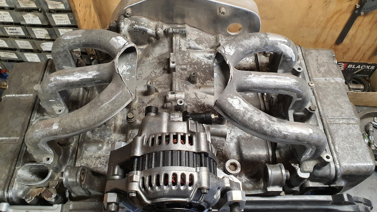
So while I plan out what my induction and exhaust setup with consist of I thought it best to get the alternator sorted.

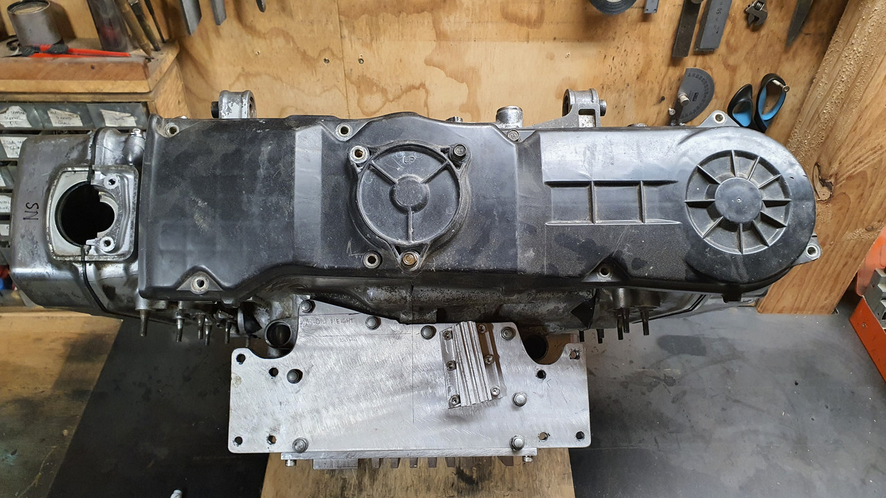
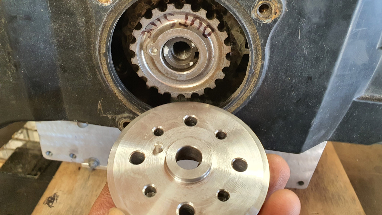
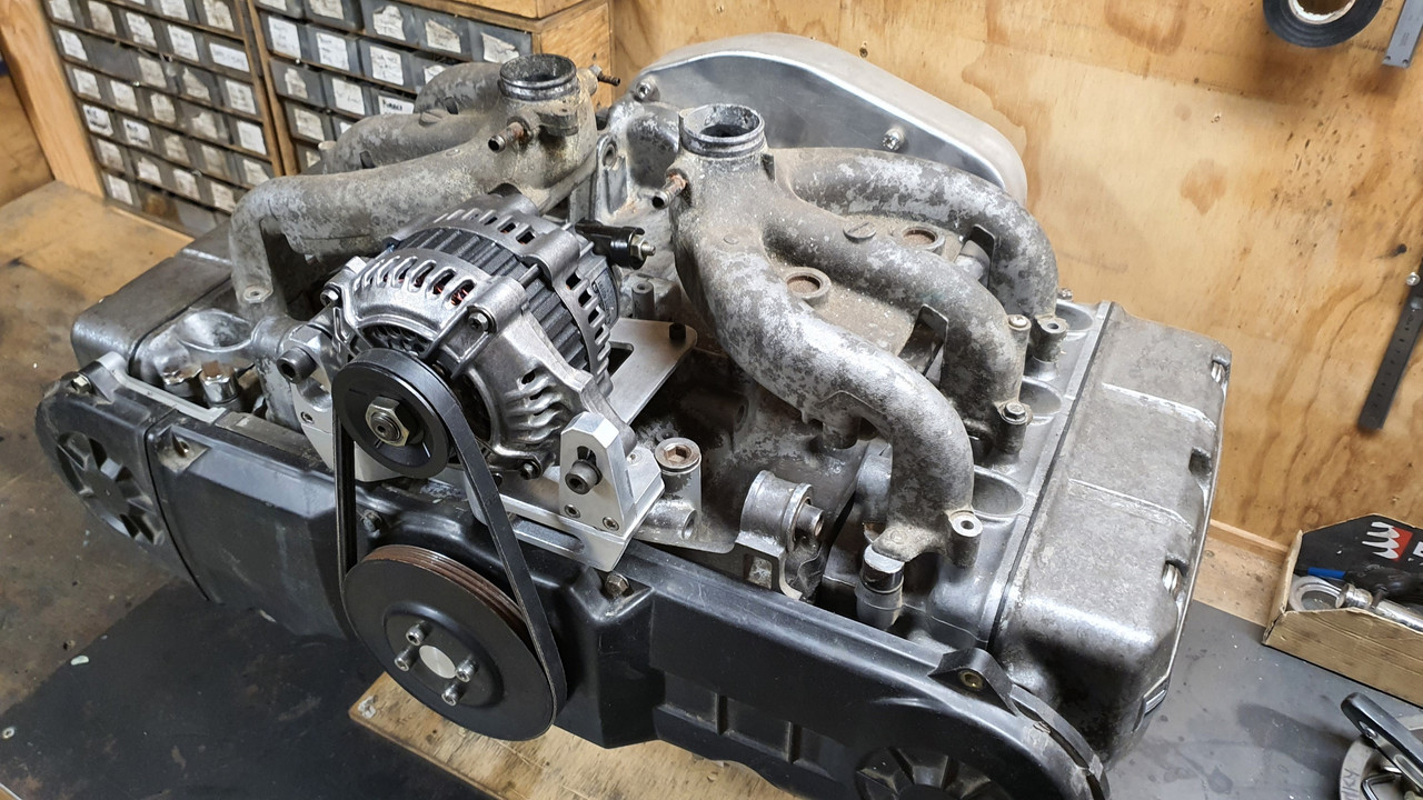
As most of you would know already the goldwing engine originally had its alternator mounted off the back of the engine on a seperate casing now removed and driven via one of the many gears that resided within this casing between the engine and the clutch area. That area is now taken up by the bellhousing I have built and the alternator has to go on the front of the engine (which now the back ? of the engine as it sits in the imp..) and be driven off a crankshaft pulley that does not exist.

This is what it looks like ..


That little round cover hides the main cambelt drive pulleys and has a belt guide plate marked with various timing marks for setting up the ignition..


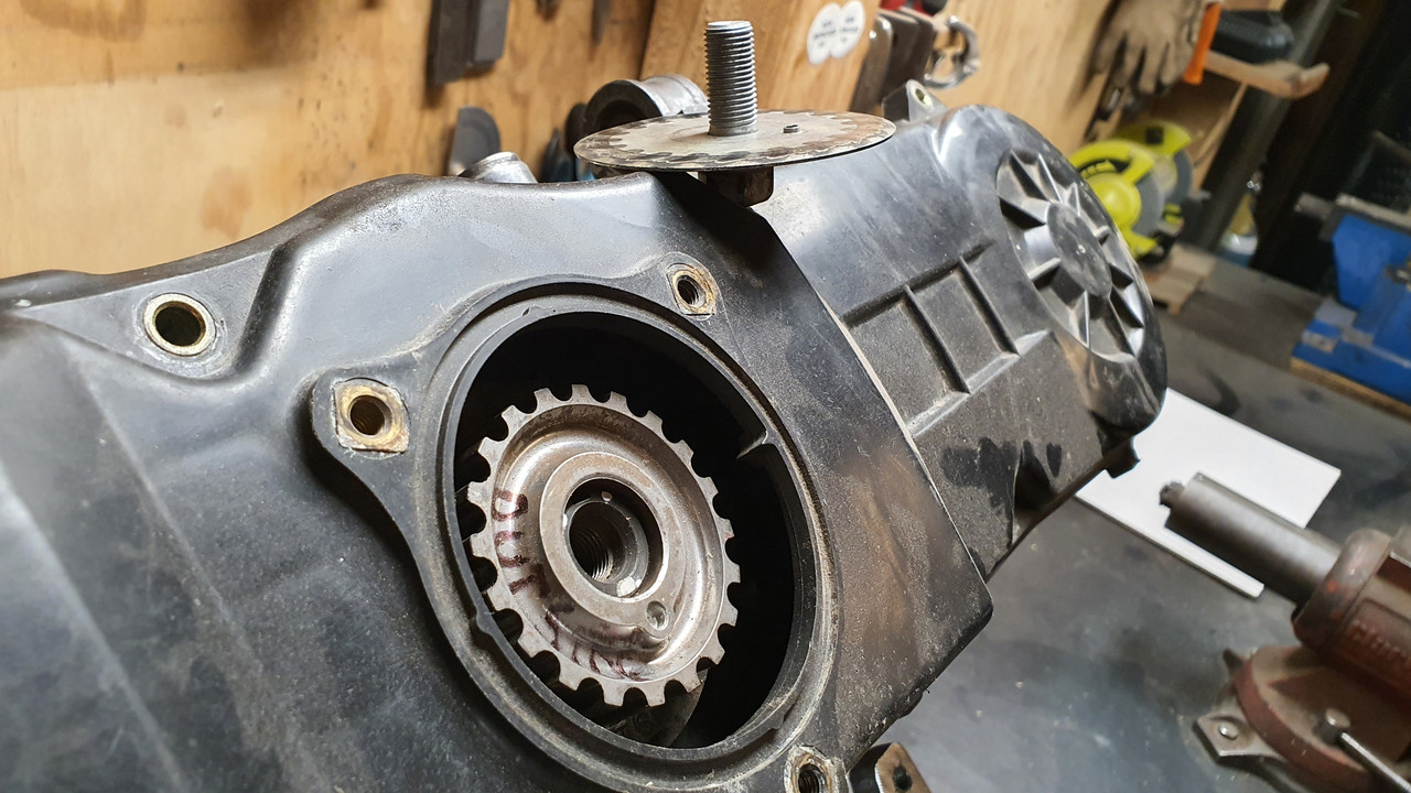
Under that pressed steel disc resides the first of the pulleys.


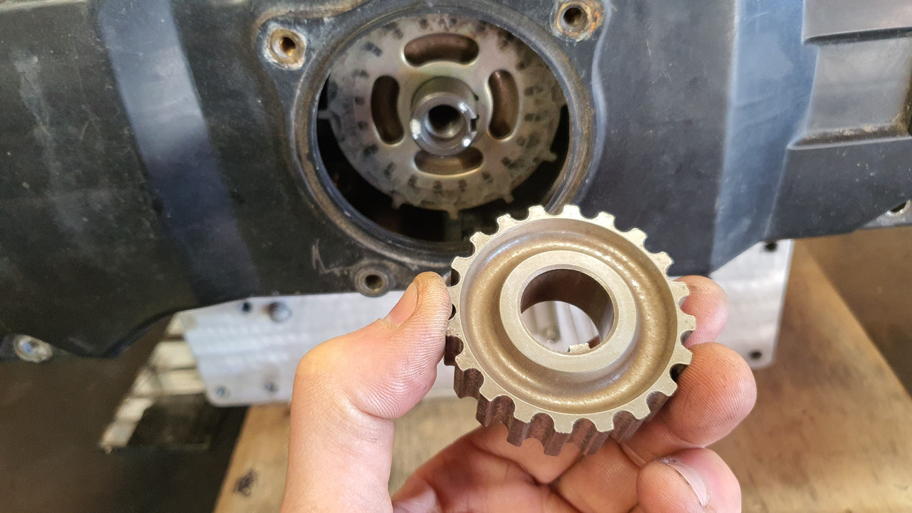
Sandwiched between the pulleys is a 12 tooth trigger wheel - handy for my planned engine management on a six. I'll replace it with a 36-1 wheel though.


So I need to machine up a few bits to allow the crank to run a mini v belt pulley and drive the Honda alternator which I had picked up at the local wreckers will sit about here...


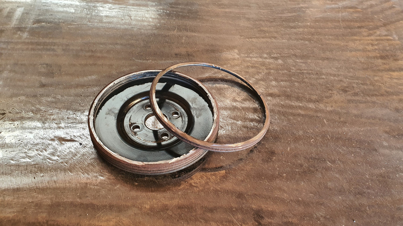
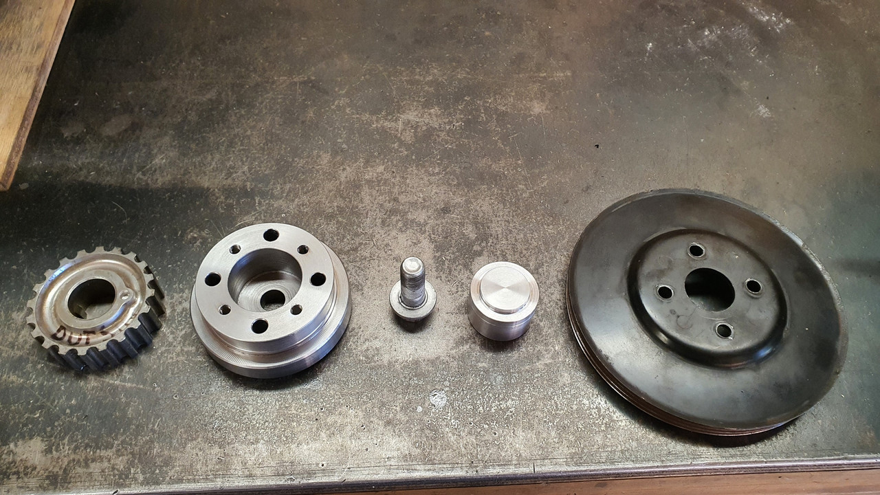
At another wreckers I found a pressed steel 5pk pulley from a power steering pump that was about the right diameter, had a flat mounting face and bolted in place with 4 little bolts. Ideal for my plan. I cut it down to suit a 3pk belt..


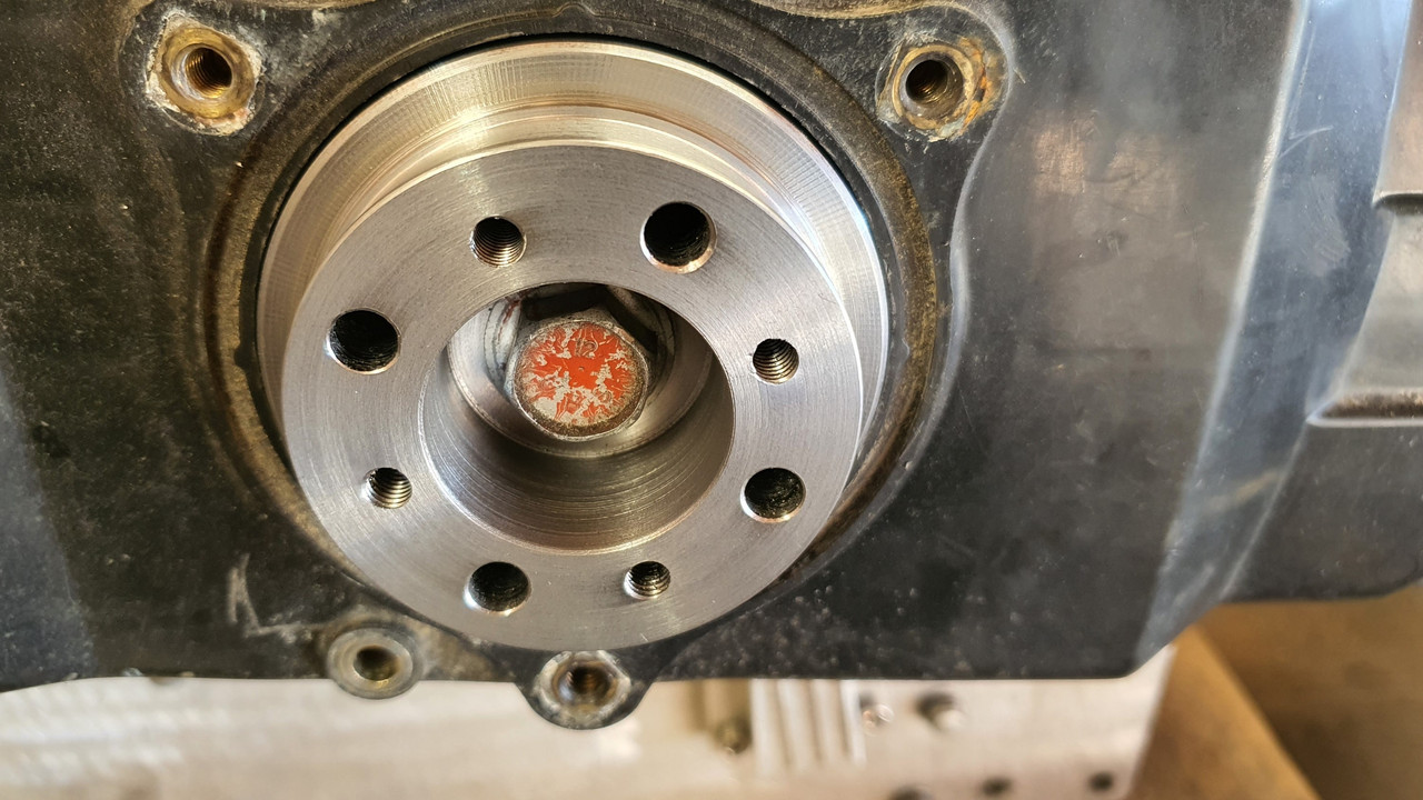
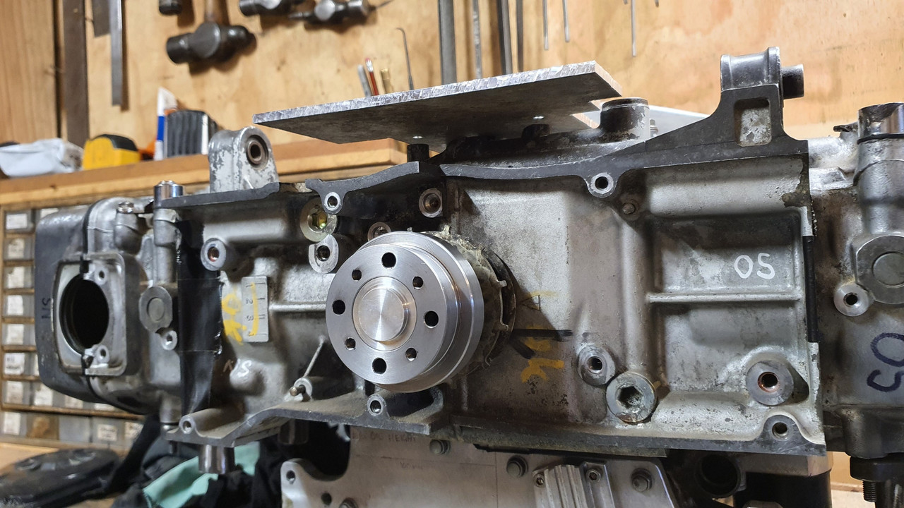
Then I popped a big lump of steel bar I luckily had left over from some other job into the lathe and machined up a hub with a locating extension on one side to match the inside of the cambelt pulley, of which which extends beyond the crankshaft nose by about 3mm. It drives , via a pin pushed into hub, off the hole in the cambelt pulley, which is there to locate the original timing plate..


The other side of this hub I bored out as far as I could whilst still allowing enough meat to bolt the pulley on.

This hub then bolts onto the crankshaft, eccentrically located by the camshaft pulley and held fast by the crankbolt..


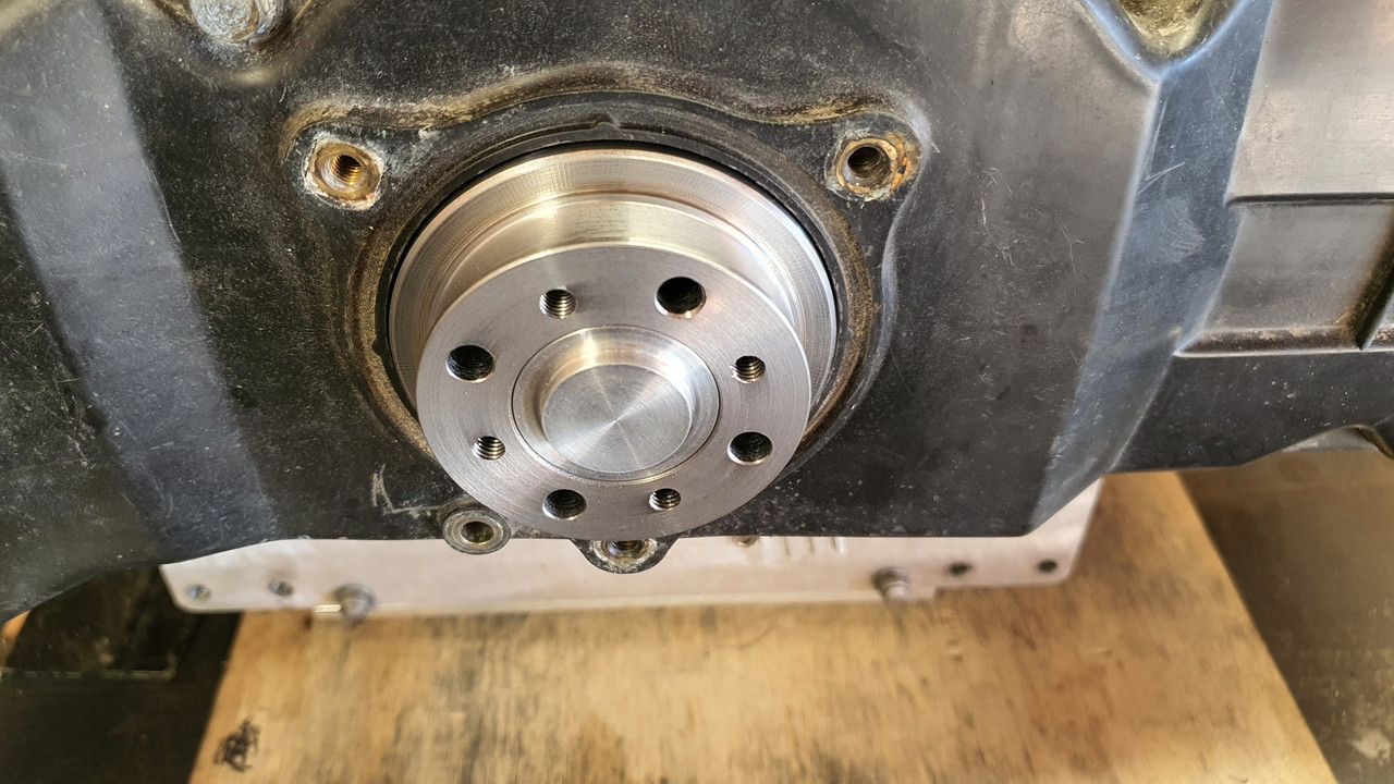
Then I machined an alloy 'plug' that fits snug into the bored out hub, machined on the end to centrally locate the steel pulley, rather then rely on the bolts..


And all lined up...

 
Discussion starter · #148 ·
So now I have a front drive pulley. Yay. Next up is making some sort of way to mount the alternator securely and not too ugly considering its going to be right there, centrally on view.

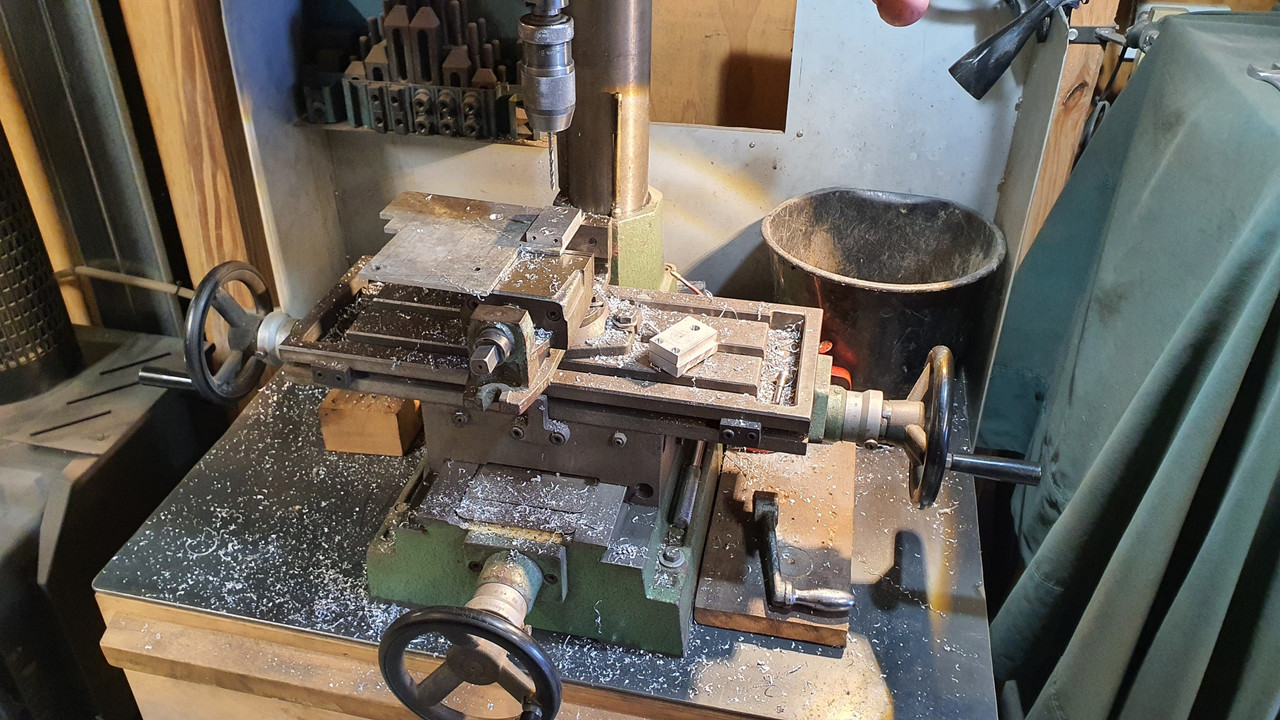
Starting the mount by making lots of little tiny bits of alloy to tread about the workshop with this tool...


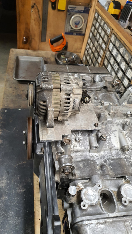
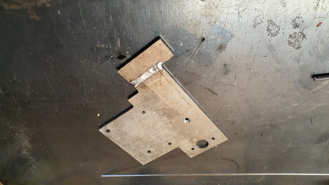
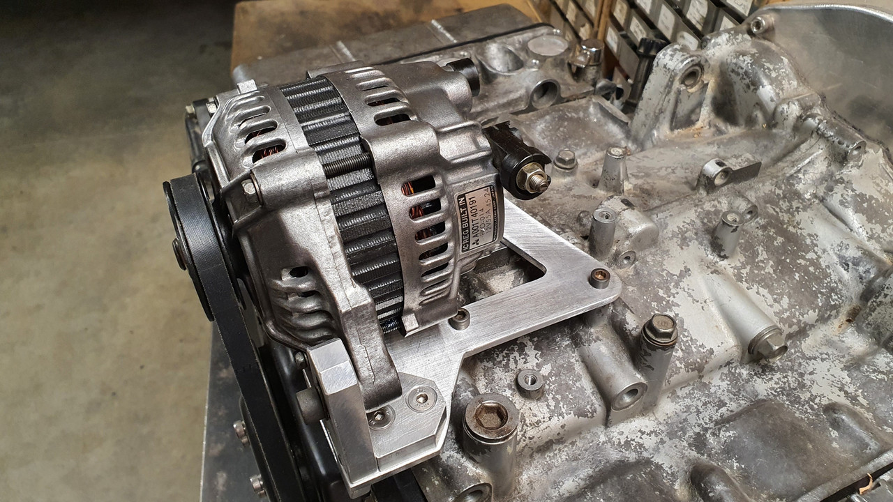
I cut some strong alloy plate and mounted it to the top of the engine using several of the conveniently placed cast in mounting points scattered about the place on top of the engine. Thanks Honda :)


I had to add a support on the front, easily bolted to the cambelt housing. Now I had a place that the alternator brackets could be bolted to. I just made it up as I went along and machined bits and pieces until I had what I was looking for. I wanted it to look a mix of between sort of factory and sort of 'race car'.

I had lots of fun making more alloy swarf..


Of course I cut my plate too narrow...


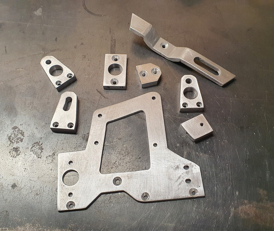
Eventually I ended up with all these bits to piece together...


Together they made this..


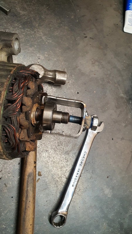
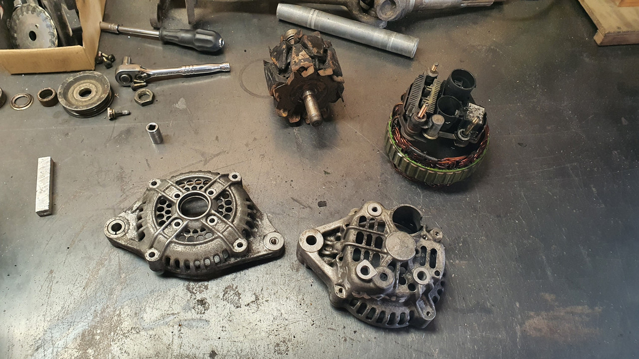
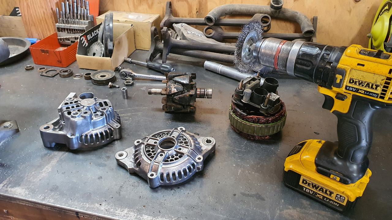
But before I plonked the alternator in place I had to clean it. It looked horrid and had obviously resided in a Honda of some ilk with some serious oil leaks. It was also a bit corroded and things didn't want to pull apart too easily. I made a bespoke little bearing puller..


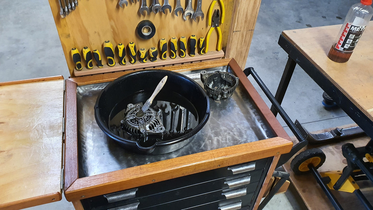
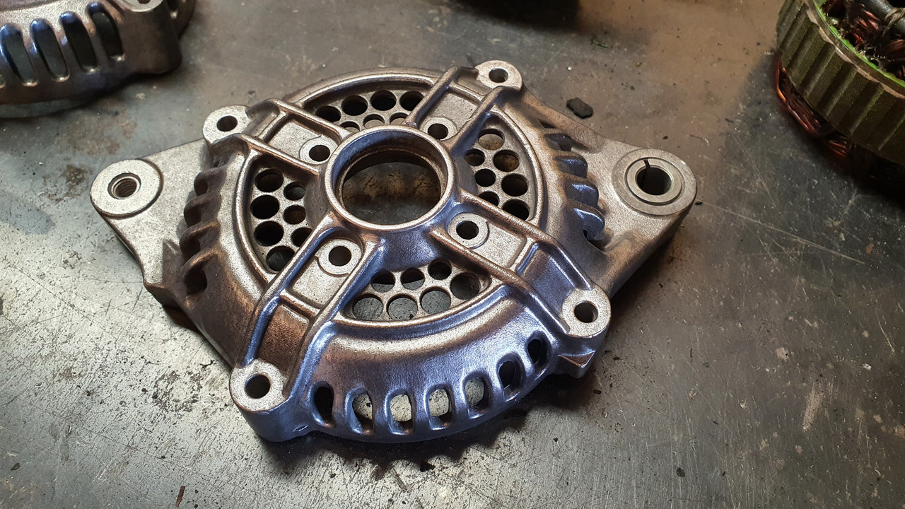
The filthy alloy castings came up nice with a petrol bath..


and even nicer with some wire brushing...


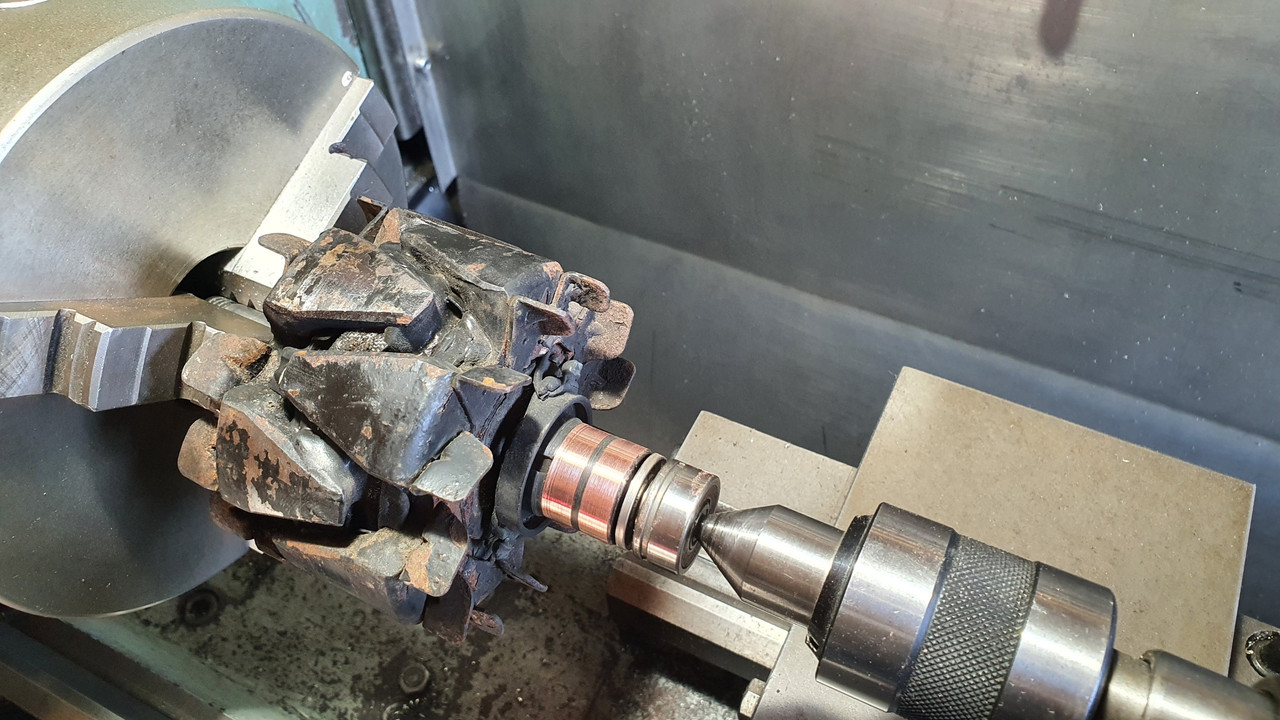
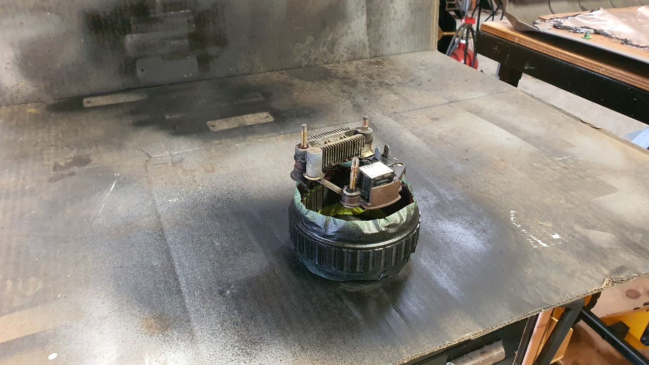
While it was apart I cleaned up the slip rings...


Painted the centre black. It will possibly be repainted in Imp blue at a later date, as a treat if the engine swap works out ok. Its just a look I quite like - call me 90s boy.


Bolted it all back together, complete with a new main bearing that I happened to have in stock (must be one of the most common bearings ever -35/15/10)

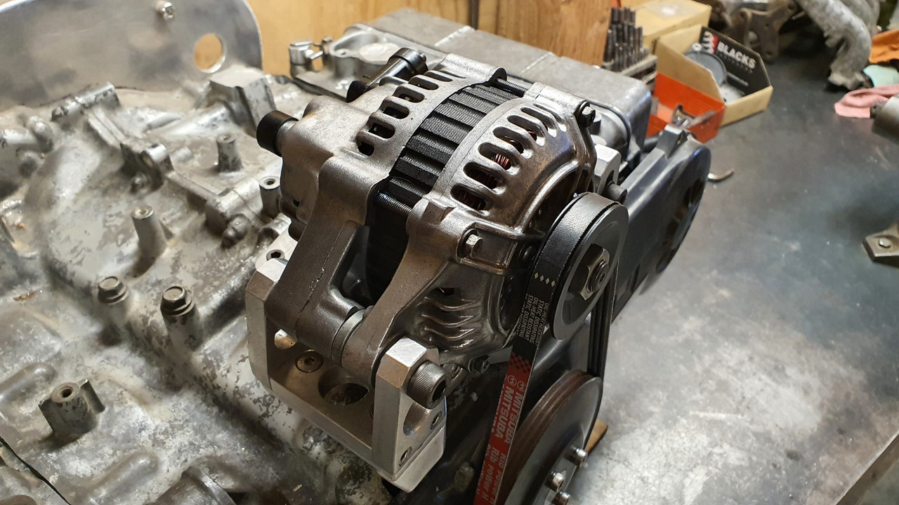
Then excitedly bolted it in place. My Honda goldwing now has a standard alternator mounted in a pretty normal fashion and it looks nice and neat...


With that sorted I can move onto making the cooling pipes and induction setup. I have still not fully made my mind up on what route I'll be taking here but I'll probably to bite the bullet and click buy now on a set of itbs so at least I have something to play with and go from there.

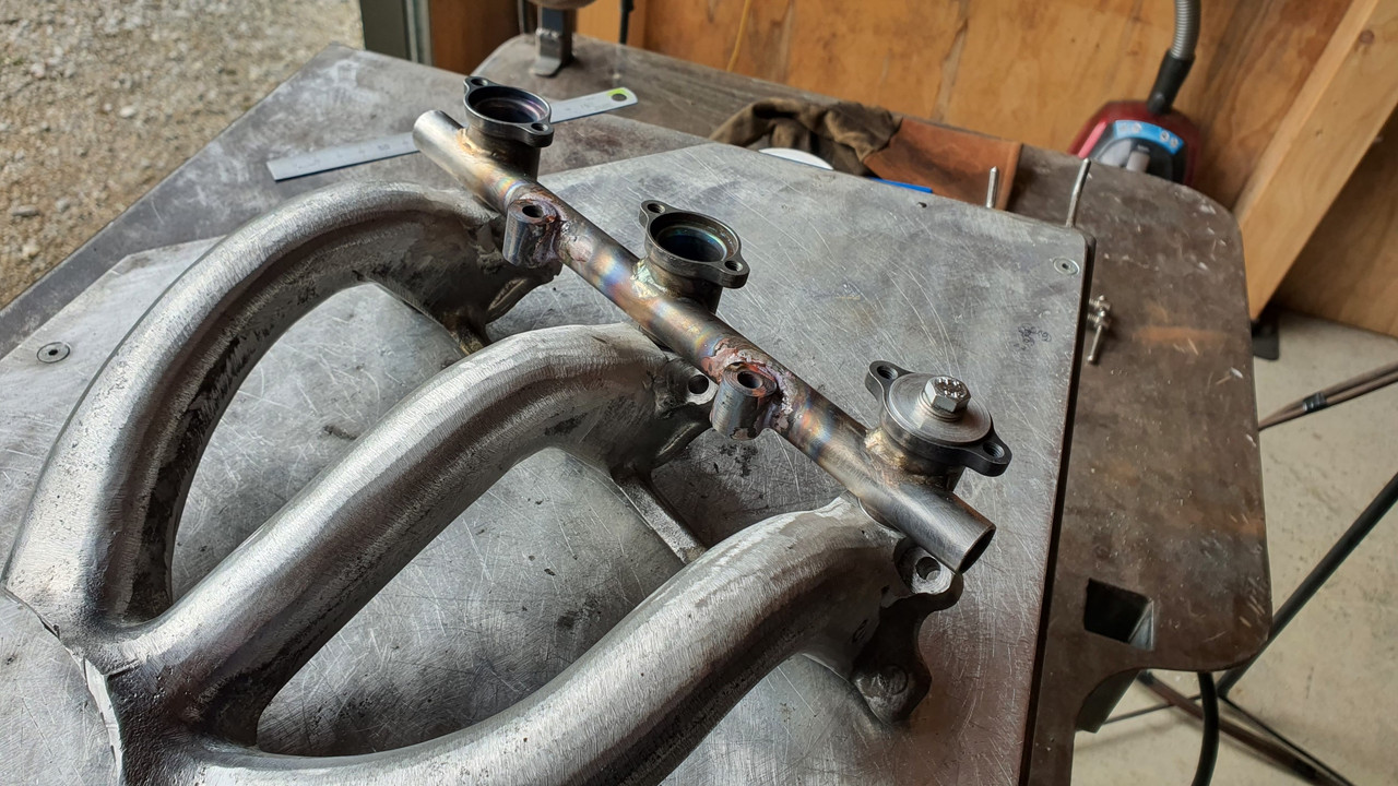
I need to find a set of suitable top feed injectors. Something around 200cc at a guess. The standard Honda goldwing 1800 items look like they'd be ok and pretty compact. I'll be making the mounting seats to suit, which I'll then weld in place on the stock intake runners. Fuel rail made to suit.
 
Very nice. There was a tent hood contraption that was pretty good at keeping a tablesaw from spraying aluminum everywhere. I can't remember the name. I usually just take my saw outside for the big messes.
 
Discussion starter · #152 ·
Thanks fellas.

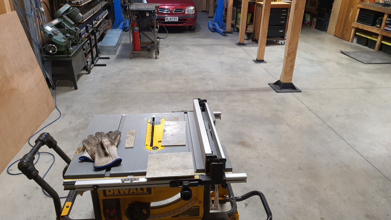
@RambozoClown yes that's right. I have one too and its handily hanging off the side of the saw frame. However for doing freehand cuts it sort of gets in the way a bit. But fear not - I wear not only googles and ear defenders but also a face mask and thick leather gloves because little shards of alloy dont feel great hitting my face/hands.
 
Discussion starter · #155 · (Edited)
Ooh its been a while. I have been tinkering away at this but other life things have popped up so this has not been high on my agenda. My dad, 89, went into hospital with pneumonia. Well he'll get looked after there.

Then he got covid in hospital. Bugger. Long story short he was on deaths door, pulled through with the aid of strong anti viral technology and great staff, slowly improved and is now in a home. His body is frail but his mind is strong. So I've been dealing with that.

Then Hannah and I got covid and it was not very fun. Being normally very fit out on the push bikes etc we have really noticed a huge loss in strength and lung efficiency. Getting better though.

So yeah.. this engine has been collecting dust. When I tested positive for covid I honestly thought I'd deal with it for a few days and then get heaps done on the engine while isolating. But my body had other ideas.

Anyway, I'm back onto it now. Quite a lot of photos to load up too.

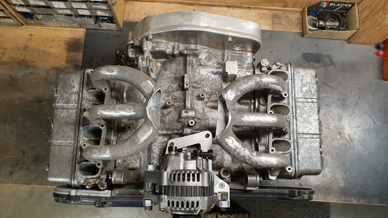
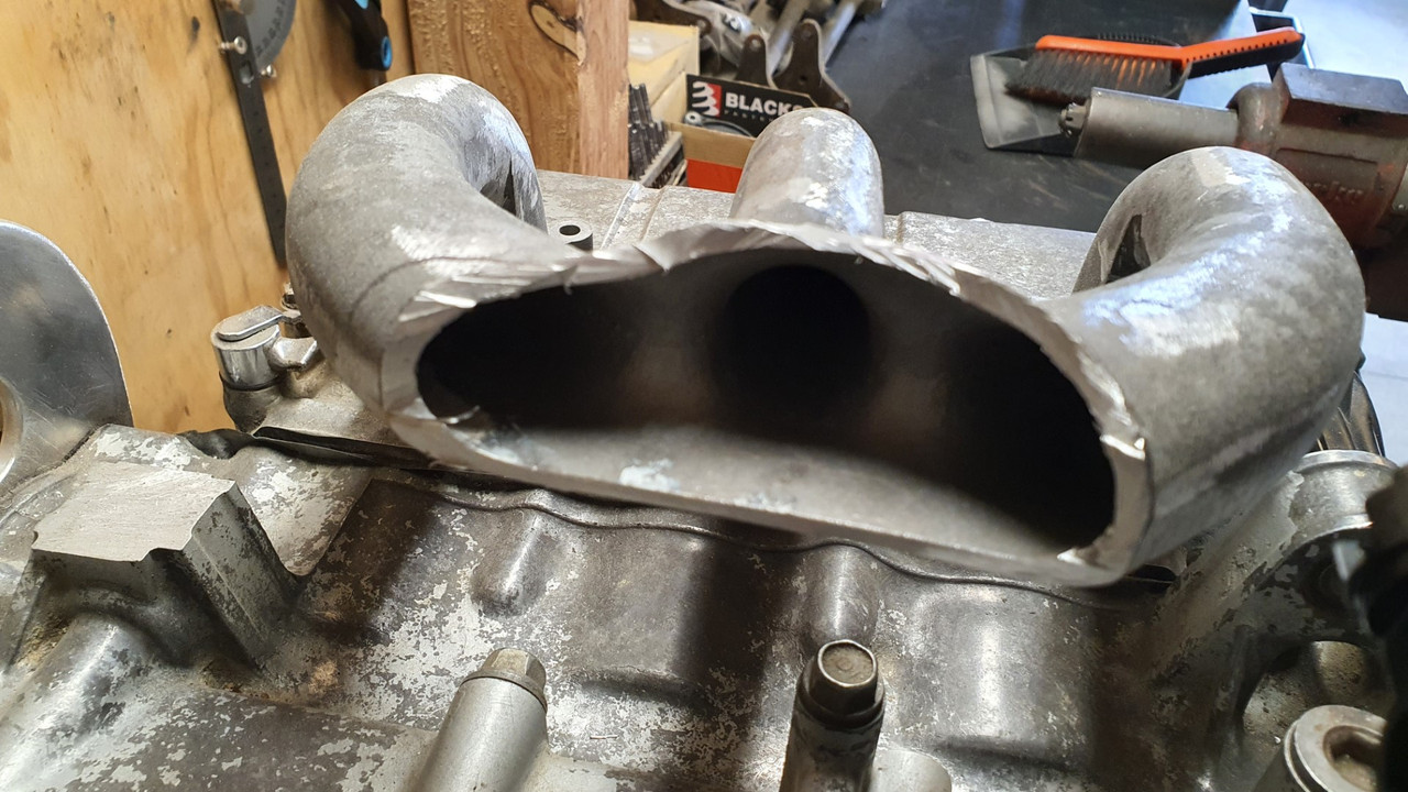
Induction time. I have decided to make something from the existing inlet runners and use a central plenum chamber with a rear facing throttle body. Try to hide the TB and use a remote pod filter to draw in cool air from somewhere other than the top of the engine bay. I have a some very funky ideas for my plenum design and have a particular look I'm chasing with the setup. Looking forward to building that. But I need to sort out injection first.

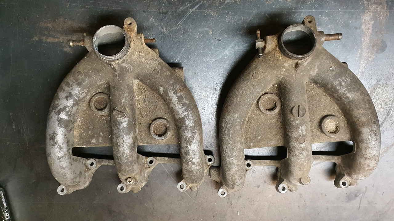
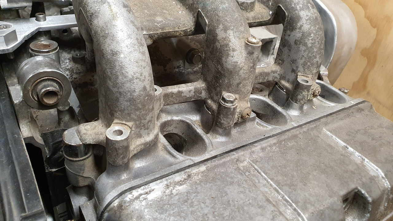
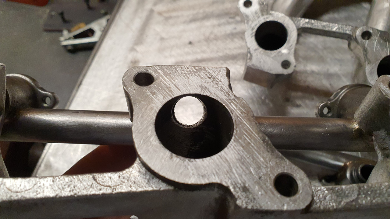
Here are the stock runners, normally fed by two carbs that sit too high and would have fouled the rear parcel shelf...


Interestingly this engine has a neat feature in that the cylinder heads are identical as are the inlet runners. They could be swapped side to side. This was going to help with my modifications when setting up the mill etc.

in place..


Note the total lack of injector bosses..


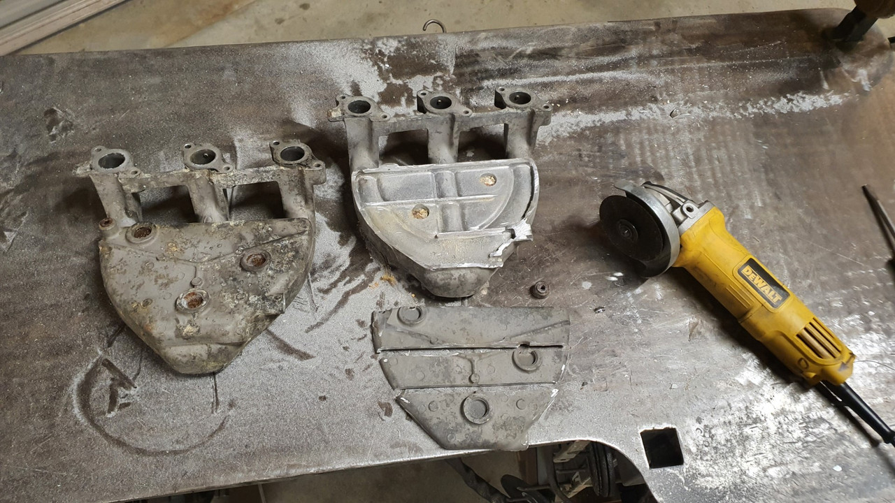
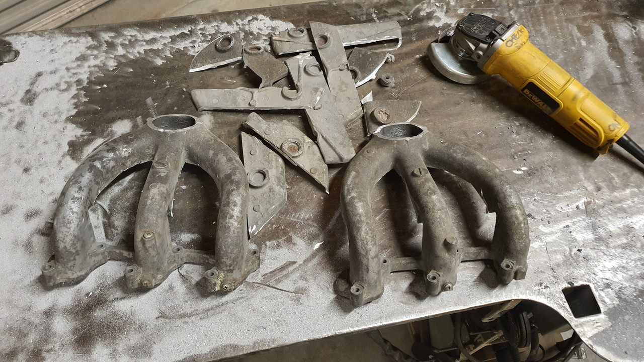
First thing was to remove the (ugly) water jacket which was not going to be needed in my setup..


Much nicer looking and lighter too...


Lots of room for a suitable sized plenum..


Very nice smooth entries into the runners..


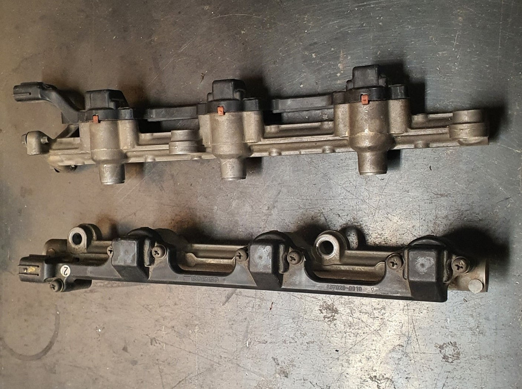
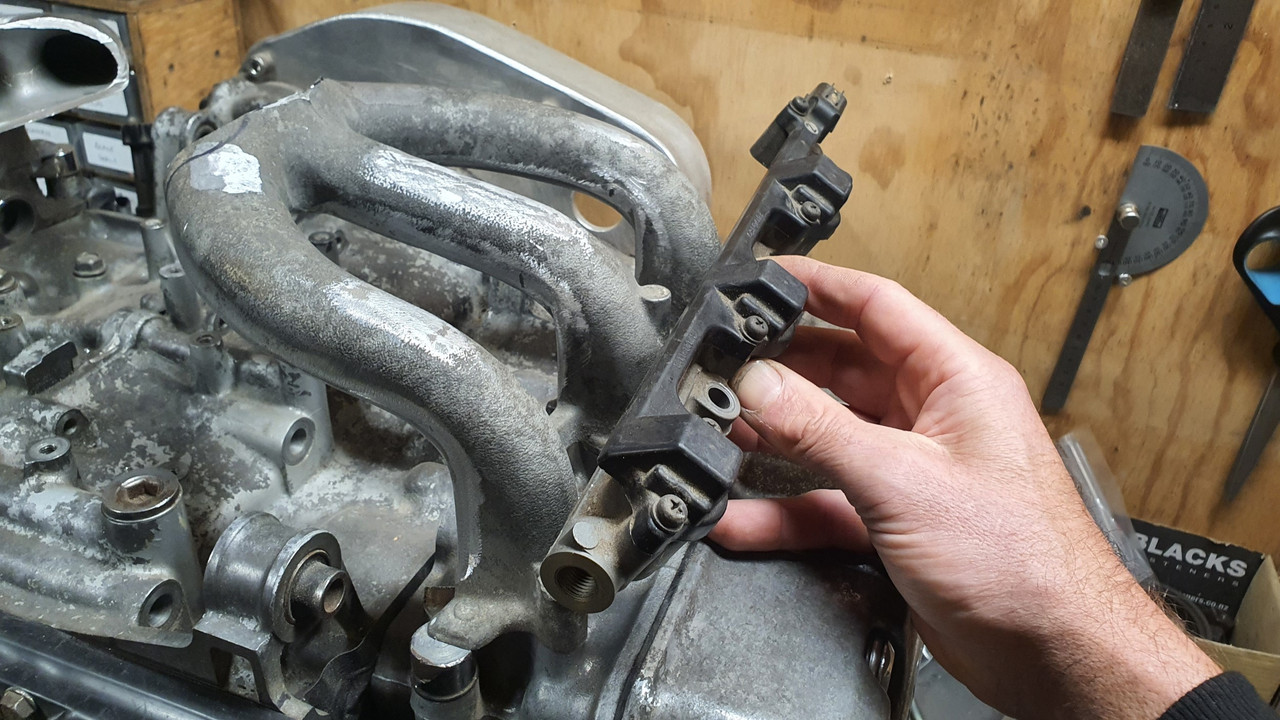
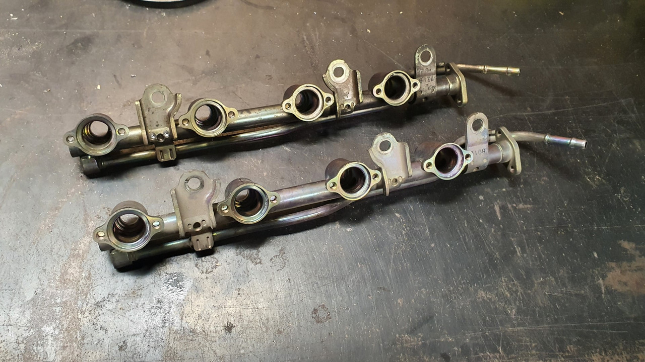
Now I needed to start looking at injector fitment. It has to be as neat and compact as possible. The spacing doesn't suit anything I could find so the rails will have to be custom. I decided against top feed injectors because they would be just too bulky. Side feed it was to be. I had a couple of ideas.

Bought another injector rail setup from a Nissan Micra K11 at the wreckers because the stock injectors have a very suitable rate (130cc) and are cheap and easy to get.


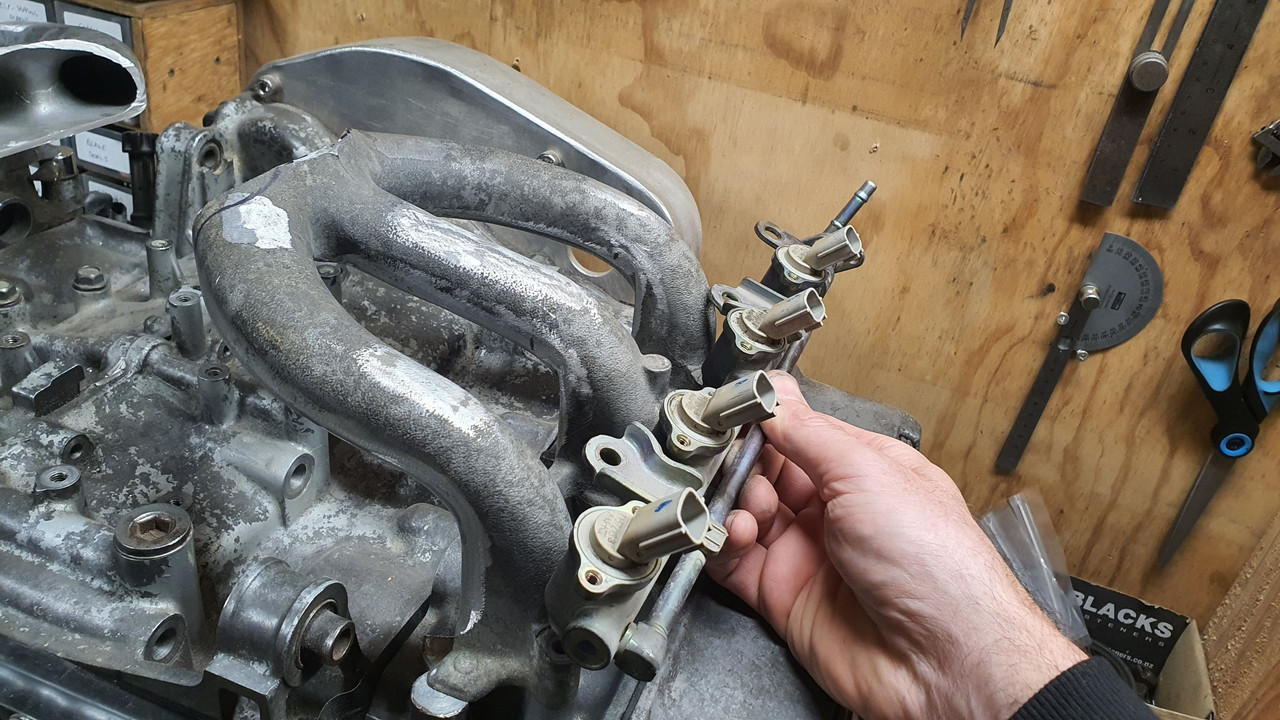
I also had a set of Mazda V6, as per fitted to my Viva, gifted to me by Steve @Transom


They were close and rather compact but it wasn't going to work without a lot of chopping and then the top caps with the wires set into the plastic would have been a pain to shorten and keep neat. Final nail for these was the injectors being just a bit high in flow rate (220cc) , running the risk of awkward tuning around idle on an engine with smaller fuel requirements.

K11 injectors it was. But the spacing is way off and they had ugly brackets all over them.


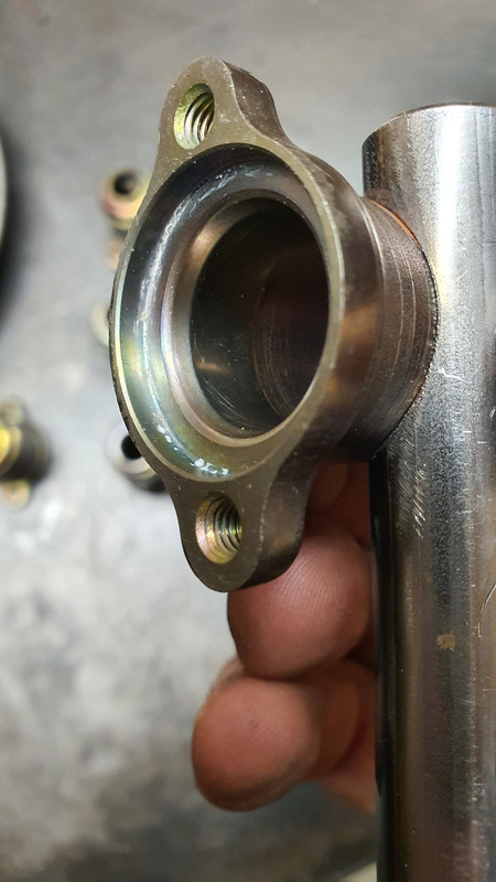
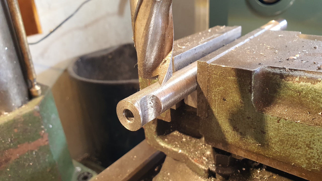
So I cut them up and ended up with just the injector housings and then played around with some 16mm tube and the mill. Bit of a test piece...


The fit was spot on..


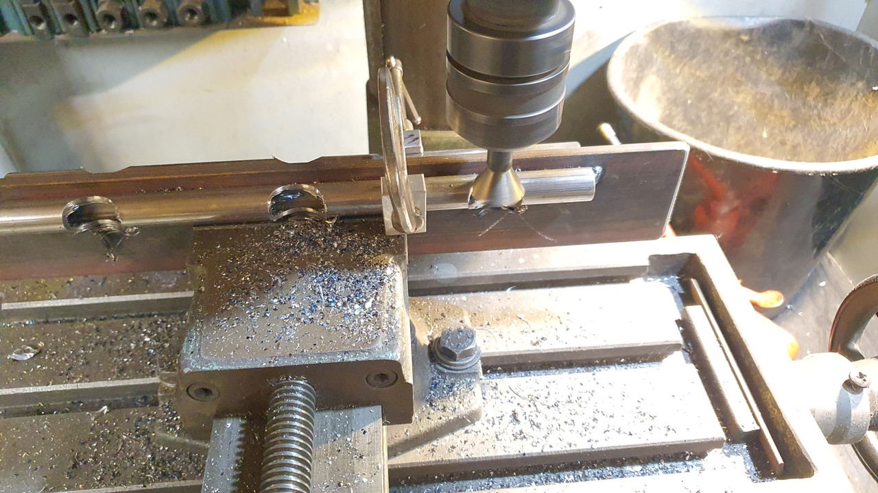
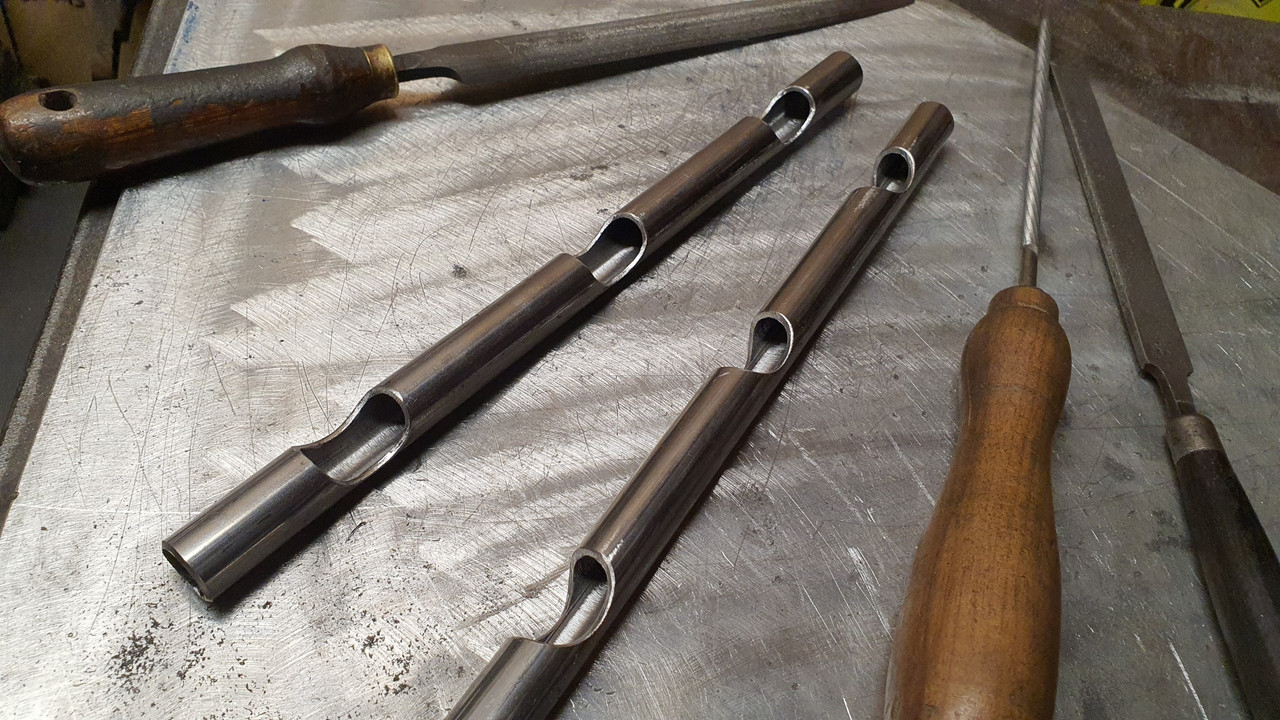
Happy with that I welded two bits of tube onto a plate of steel and carefully milled the tubes, spaced to suit the inlet spacing...


a tidy up removing sharp edges with files and they came up neat..


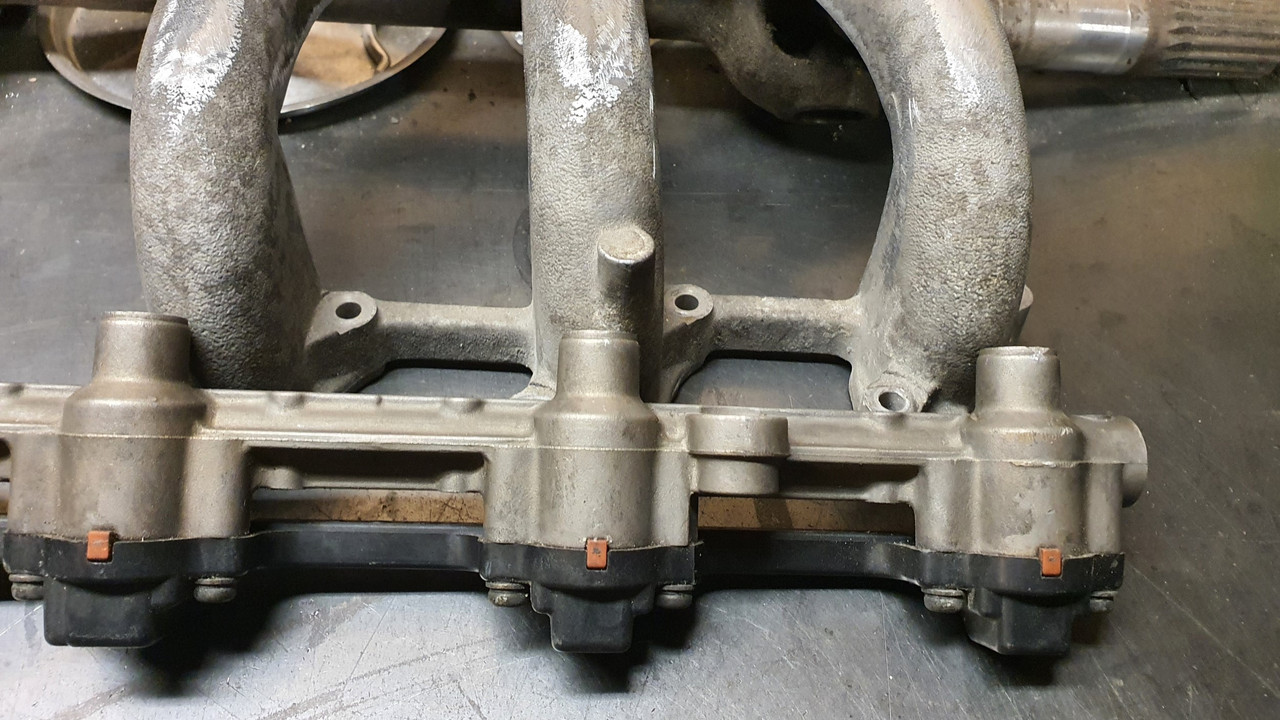
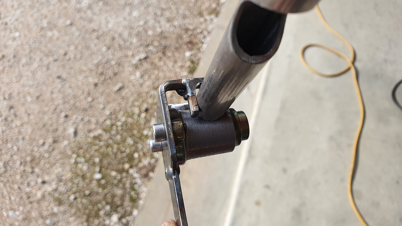
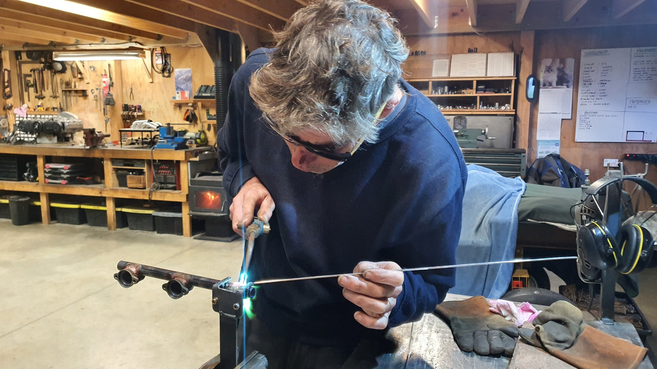
I made a little jig to hold the injector housings onto the rail with the correct spacing so I could braze them in place..


Then out with the oxy acetylene and brazed them in place with silver solder. Note my sore nose where I had smacked it with a large branch when cleaning up a fallen tree. Hurty...


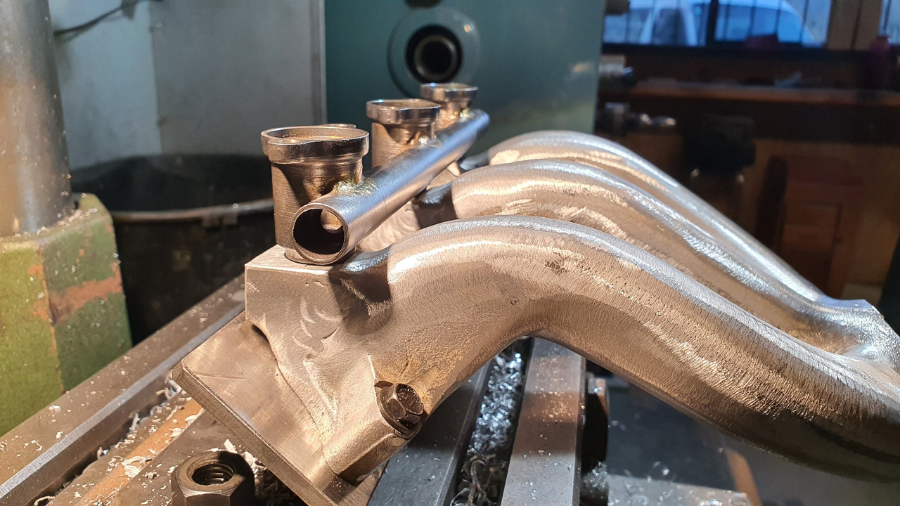
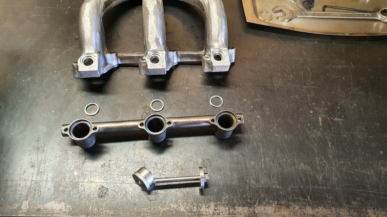
Now I have some side feed rails with the correct spacing :)
 
Discussion starter · #156 · (Edited)
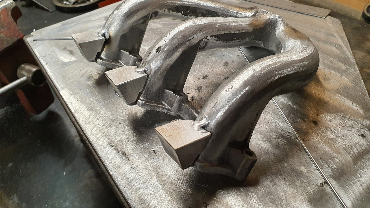
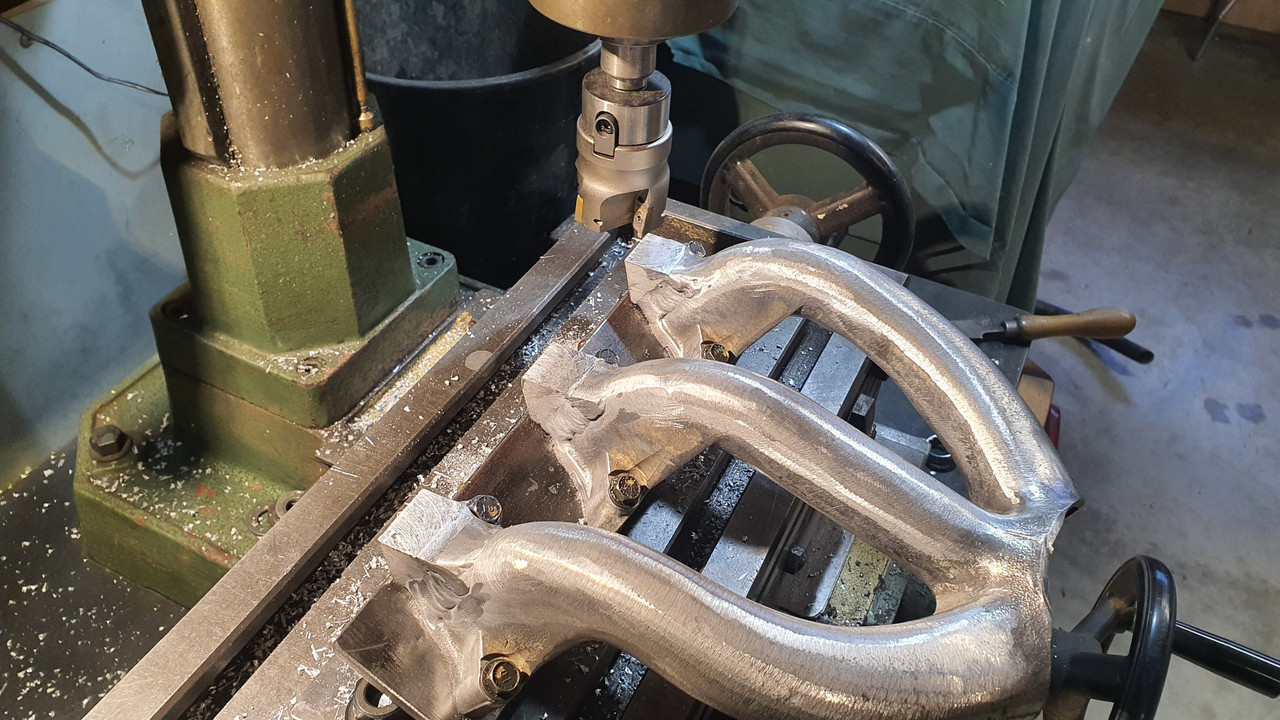
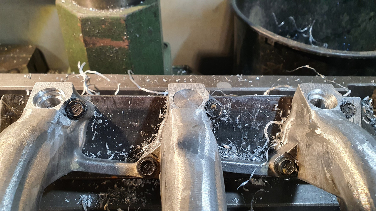
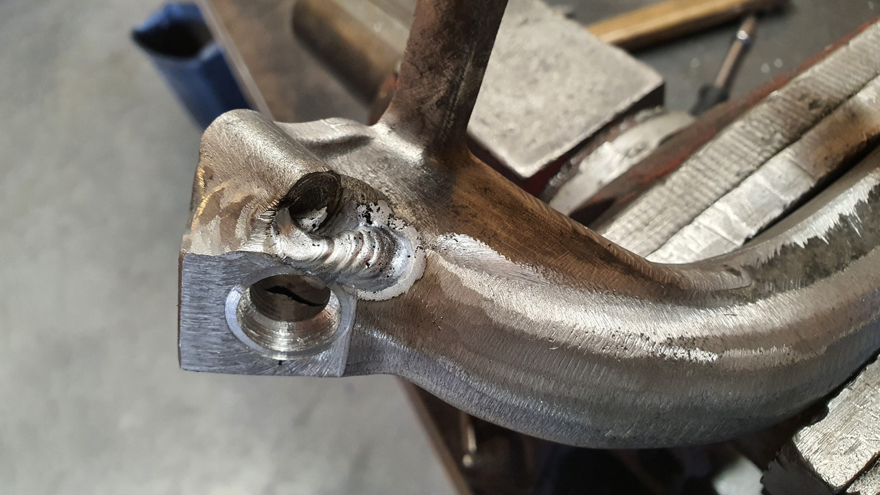
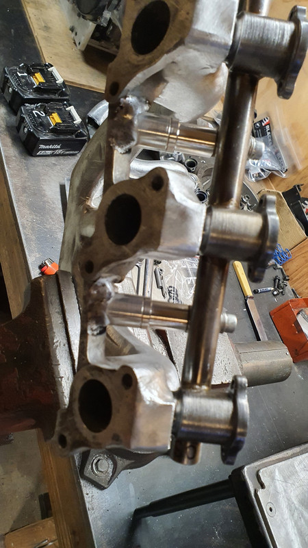
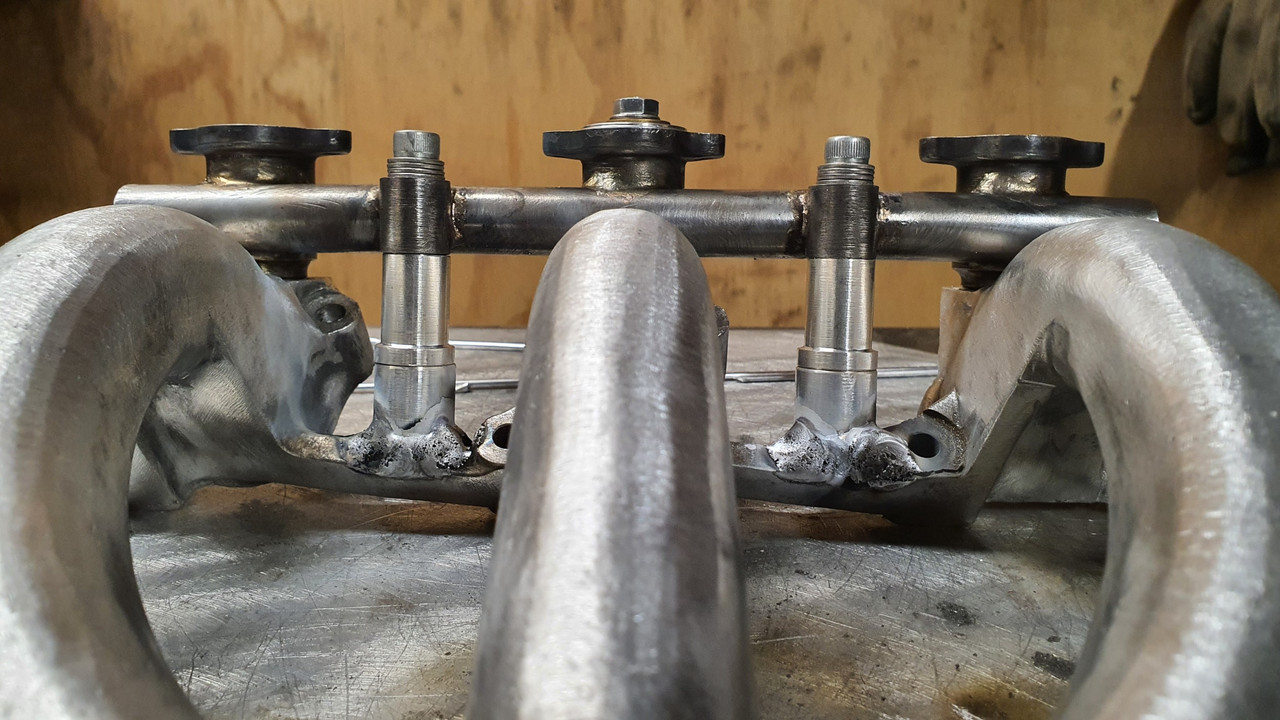
Next job was to create a place for them to fit. I needed to add some bosses to the inlet manifold and get the angle just right so the injectors would end up pointing as close to the back of the valve heads as possible. I cut up some chunks from a large bar of alloy. Then I milled them down to suit and tacked them in place...


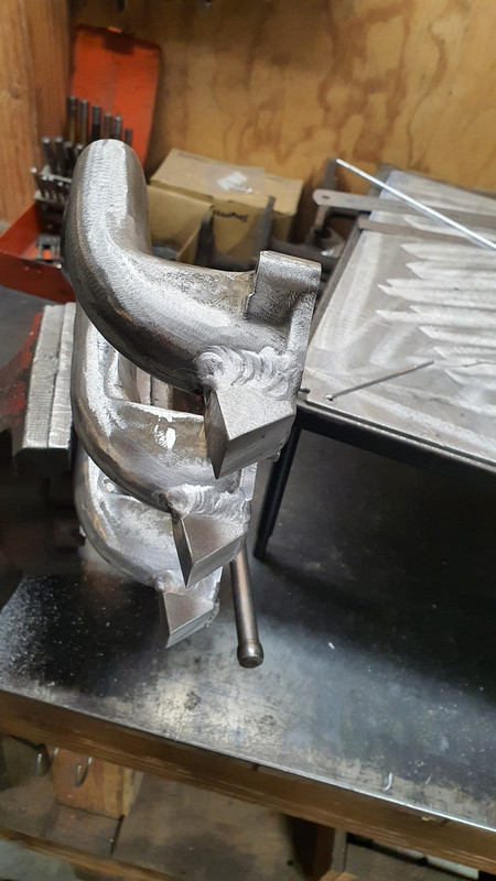
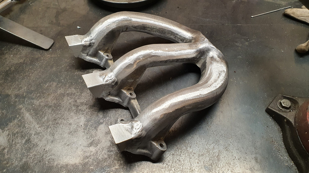
Happy they were located correctly I fully welded them in place. The inlet casting was luckily of pretty decent quality and welded nice enough..


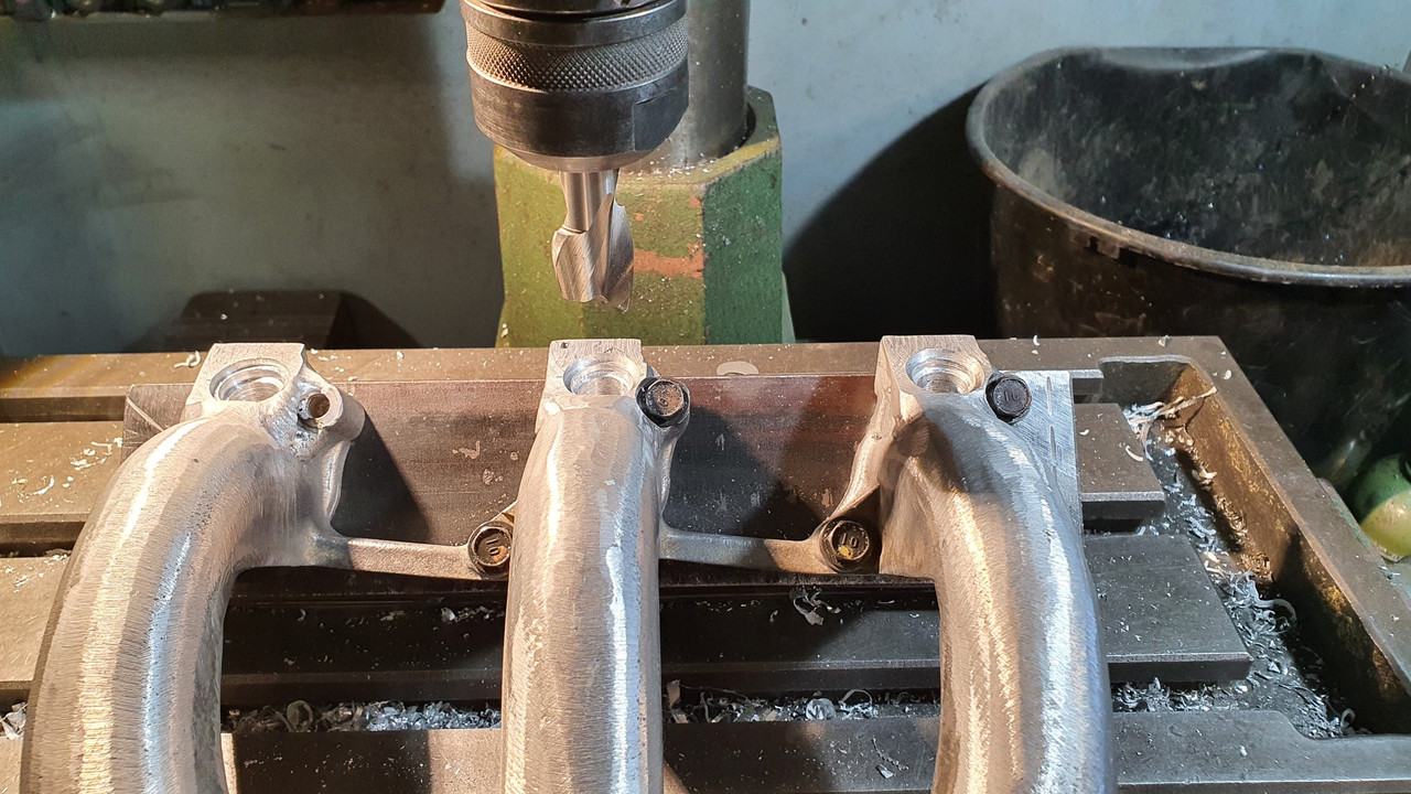
With them welded up and solid I could machine the bosses down in one hit, levelling them off at the correct angle and making sure the faces all lined up. I made a steel jig, set at the angle to suit (because my drill mill doesn't have an head adjustable for angle... oh how I'd love a larger knee mill)


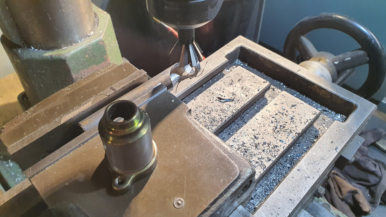
Now I was able to carefully mark and drill out the injector holes, then spot face the O-ring seats..


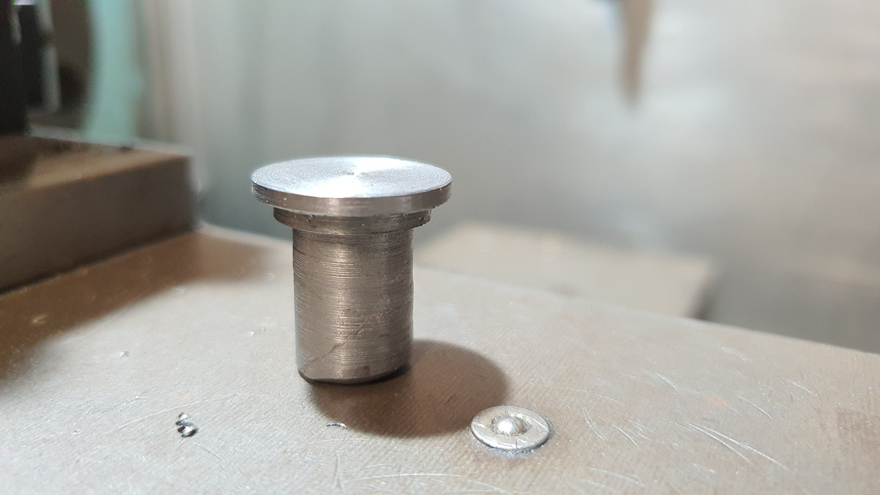
In order to aid with with marking and checking them I machined up a little button that fitted perfectly into the injector holes...


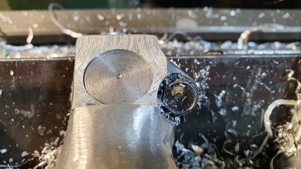
Annoyingly (silly me) I marked to first hole off wrong by 1mm and by the time I was at the last boss on that side I had to add some weld to make sure there was enough meat to house the O-ring...


I learned something and didn't repeat the mistake on the other side
:)
 
Discussion starter · #157 ·
Now I had injector bosses and the holes were pointing in the right place..


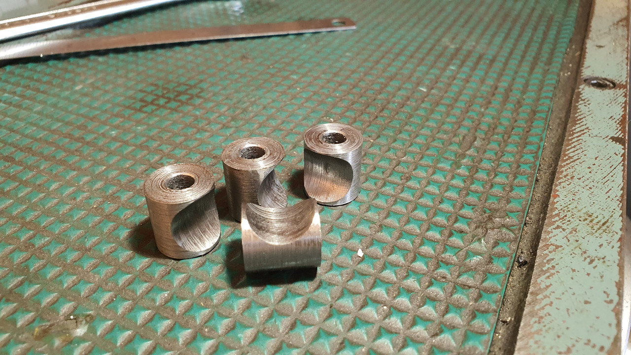
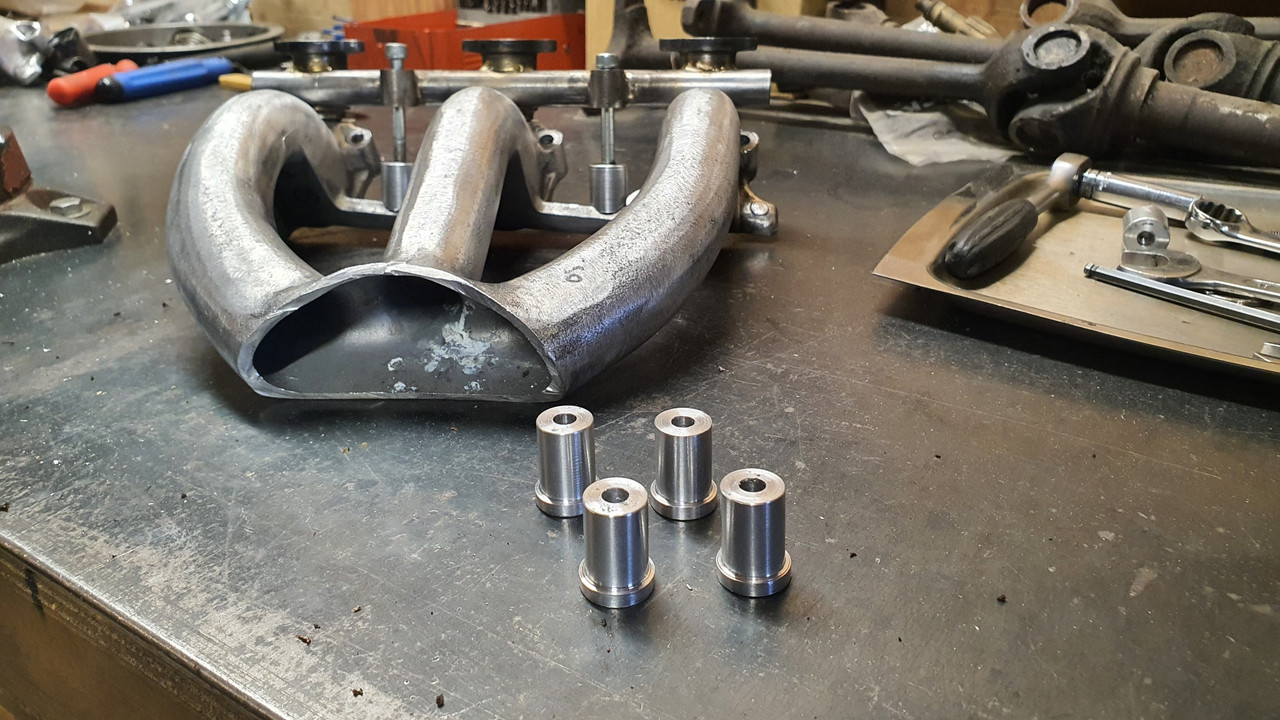
I have to hold them down in place though. So I made up some little steel bolt bosses..


Brazed them in place..


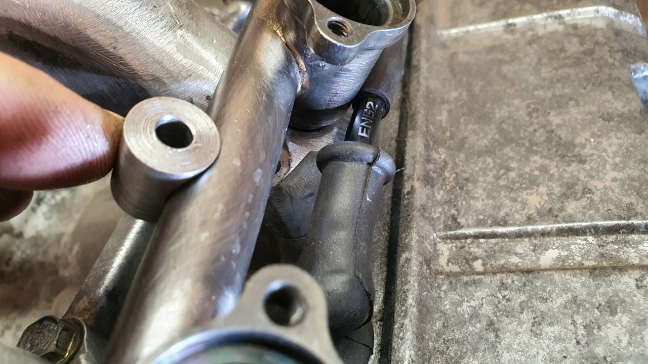
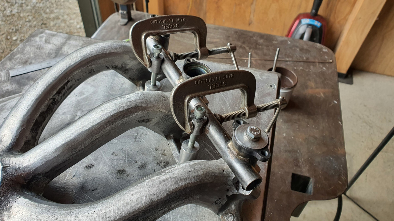
Machined up some bits of alloy, tapped out to suit the bolts and some spacers for between. Made a little clamp thingee to hold the injector rails in place along with some alloy O-rings (because well.. the rubber ones would probably have melted when I was welding)

Pics explain it fine..


Phew. That's that! Up to date now. Next thing is to design and build the plenum chamber. I'm going to have some fun with this bit. It's not going to be simple because I have a certain look I want along with a fun idea I have in mind.
 
Your doing amazing work and engineering on this project. I hope you consider using the chrome Valkyrie timing belt and valve covers to accent all your handiwork.

I do have wonder about welding the two intakes into one piece. Will it expand at the same rate as the engine block/heads , Could that be the reason for separate manifolds?
 
Discussion starter · #160 ·
I do have wonder about welding the two intakes into one piece. Will it expand at the same rate as the engine block/heads , Could that be the reason for separate manifolds?
Yeah expansion is one thing I have been wondering about. The plenum wont be welded in place though. It'll be a modular setup, bolted with socket head bolts between two flanges. There will have to be gaskets involved which will most likely be some sort of sheet rubber. If I can allow movement there, without bolts coming loose then it should be ok. Only one way to find out...

Subaru flat fours run a very similar manifold to what I'm building but in one piece. Those engines are a bit wider too and all alloy in construction. The manifolds are quite sturdy to deal with boost...

Image
 
141 - 160 of 543 Posts