Hi all,
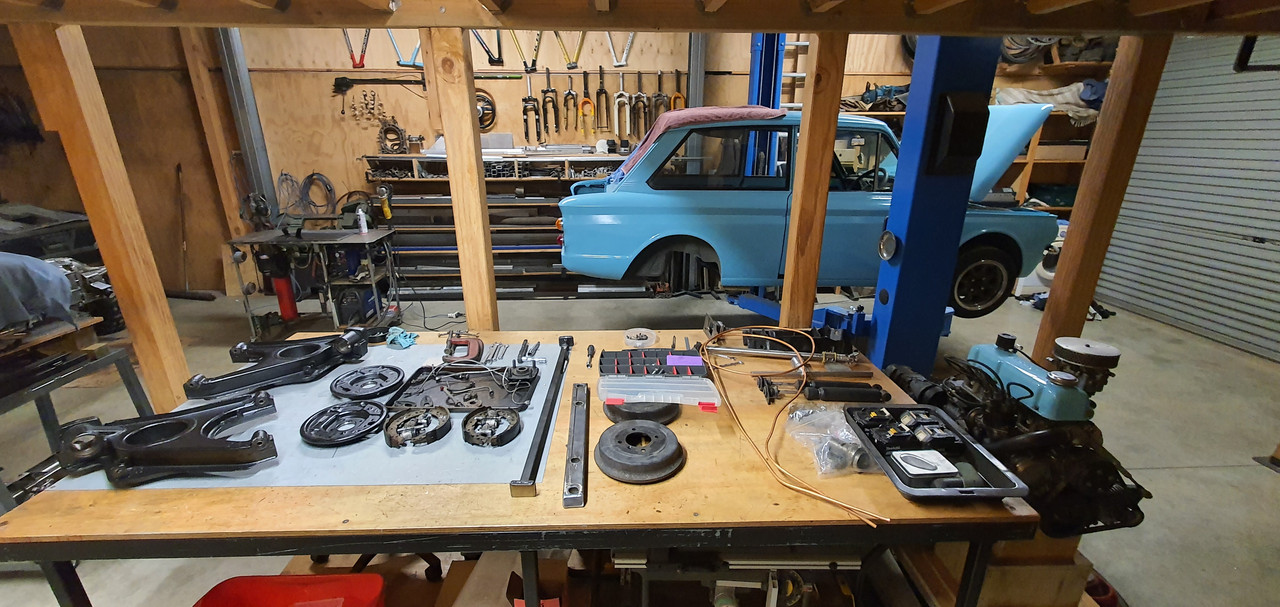
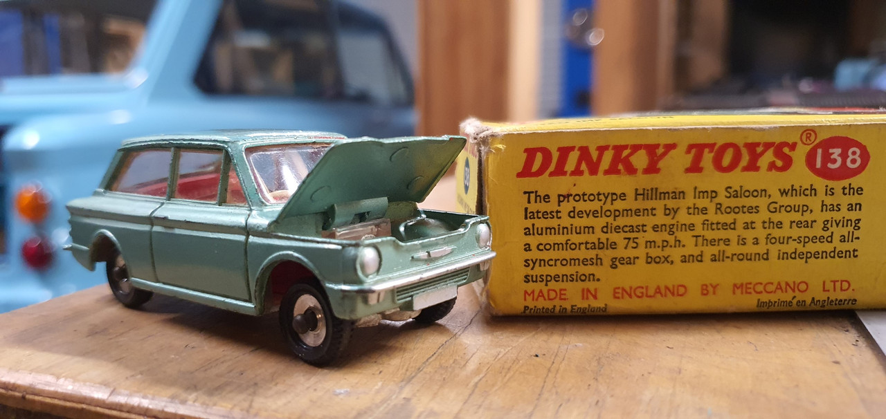
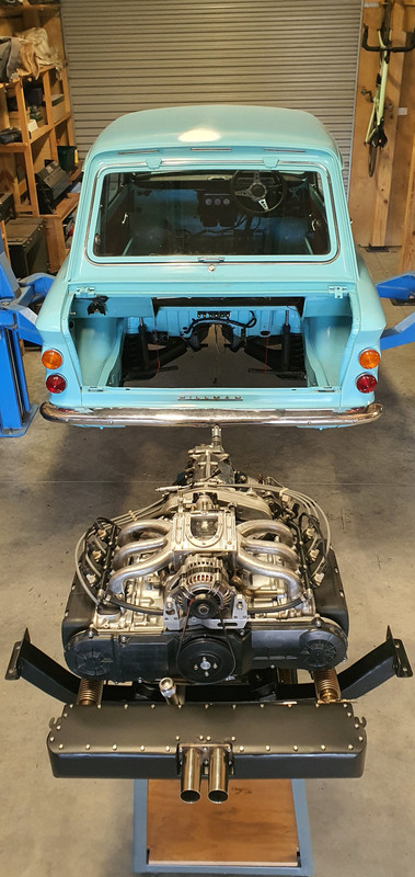
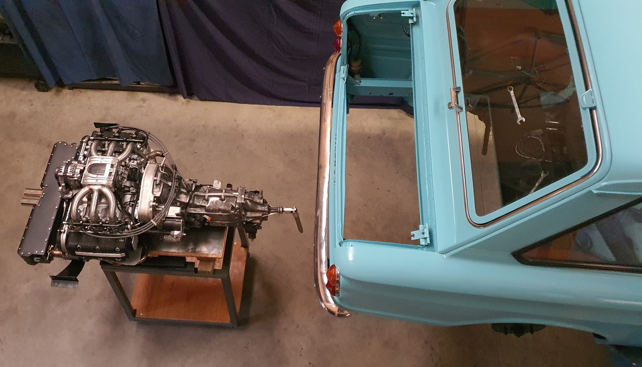
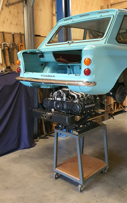
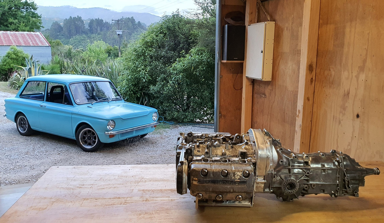
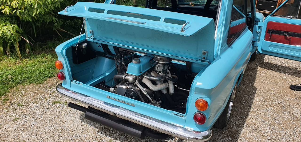
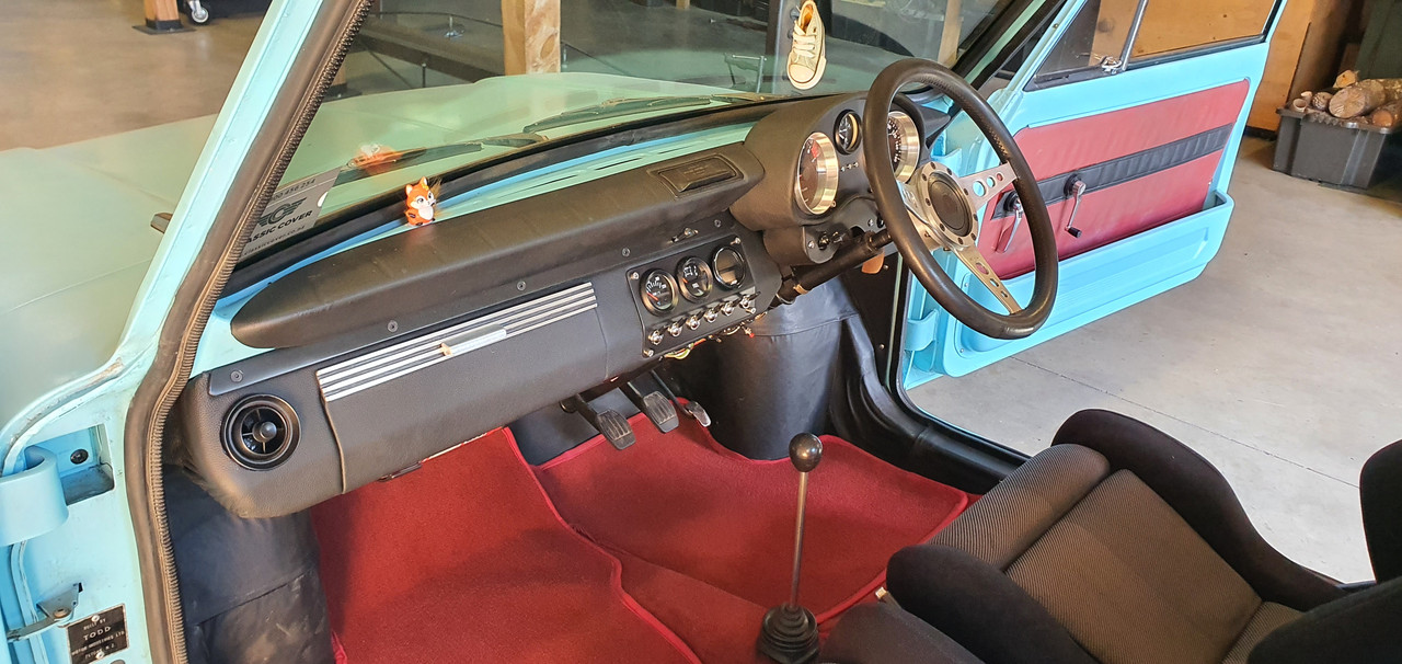
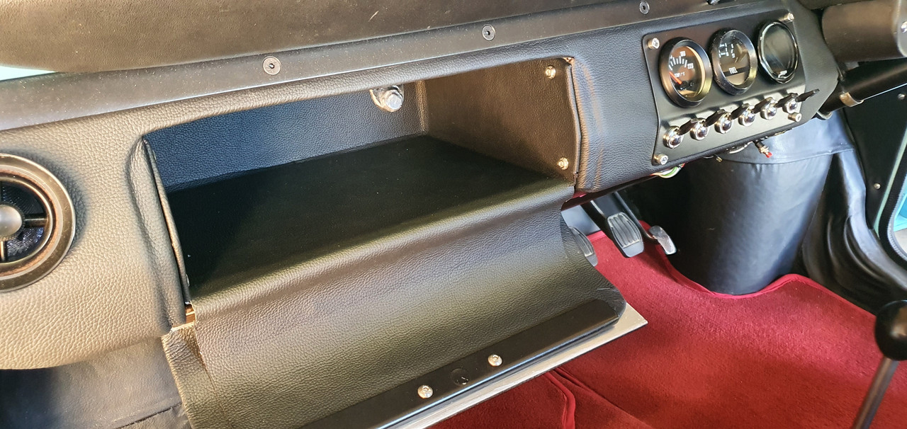
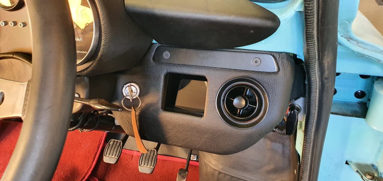
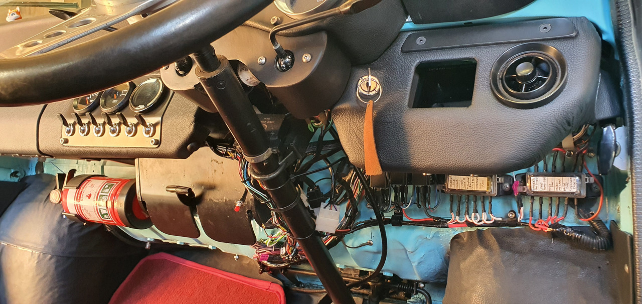
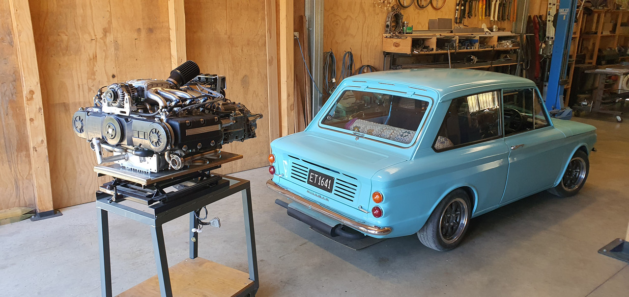
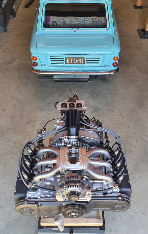
Down here in New Zealand I own this little 1965 Hillman Imp that I restored from Feb 2018. I am now looking into the possibilty of fitting a 1990 Honda Goldwing GL1500 engine to potentially build my very own baby 911")
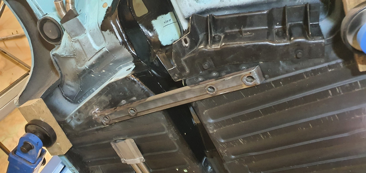
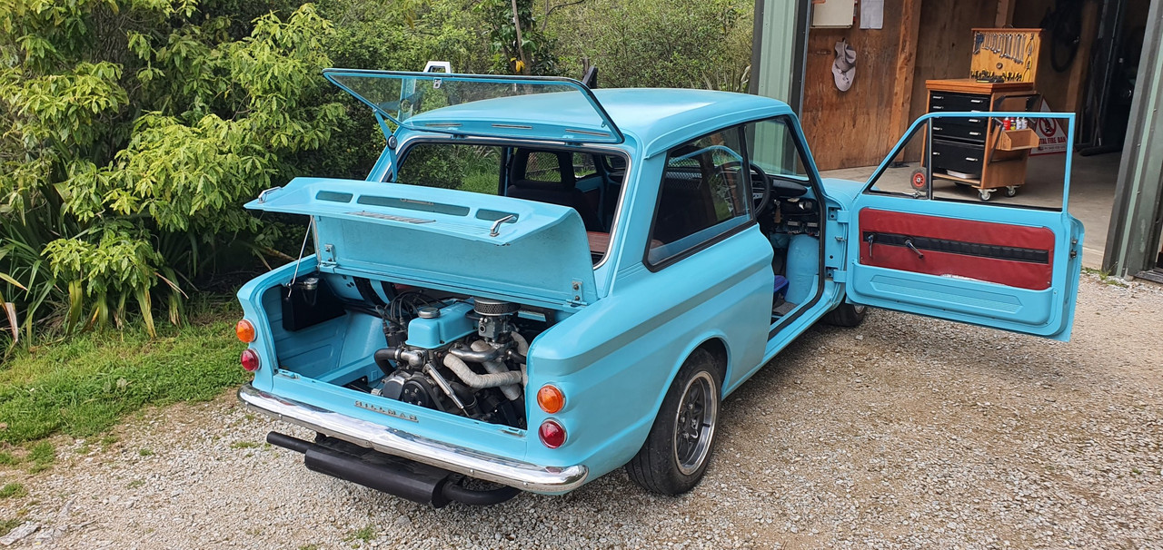
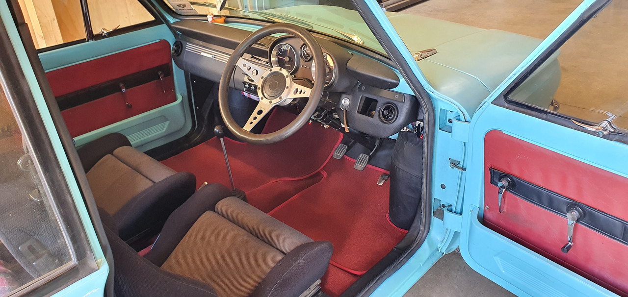
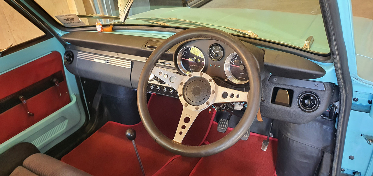
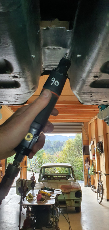
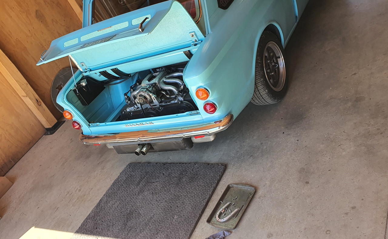
This is my Imp...

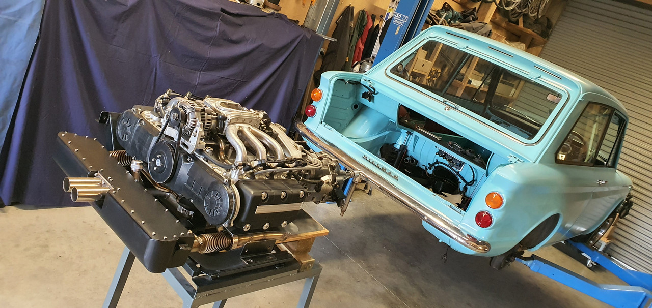
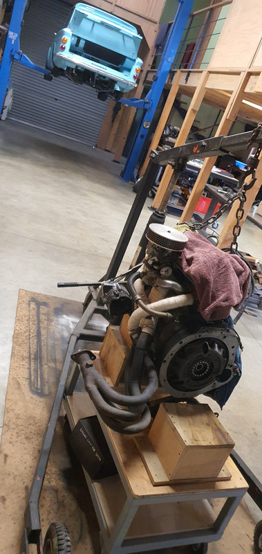
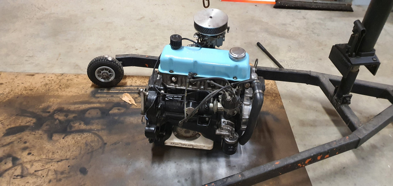
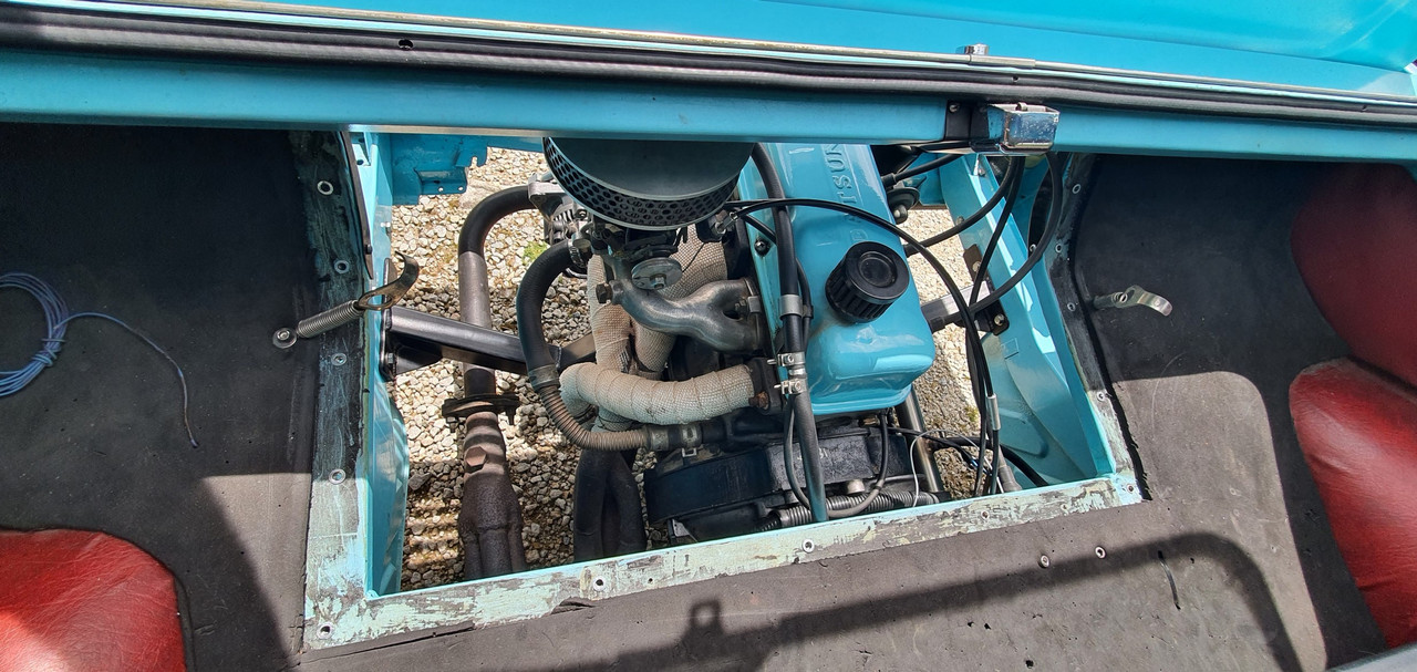
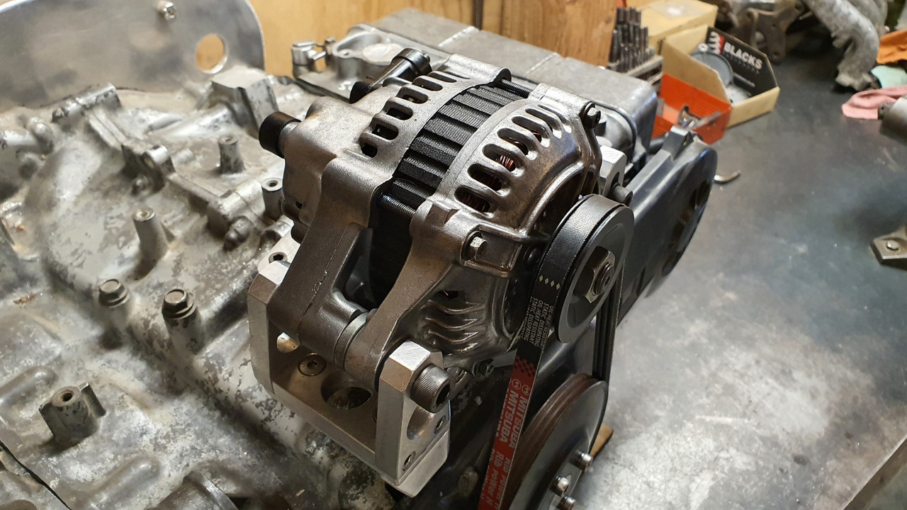
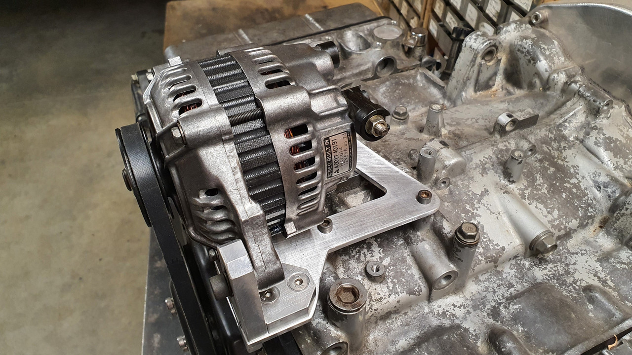
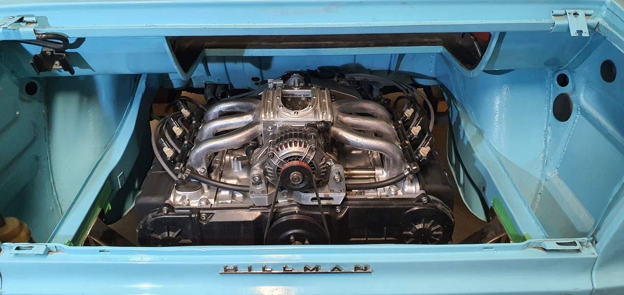
Here's the Datsun 1200 engine currently fitted...

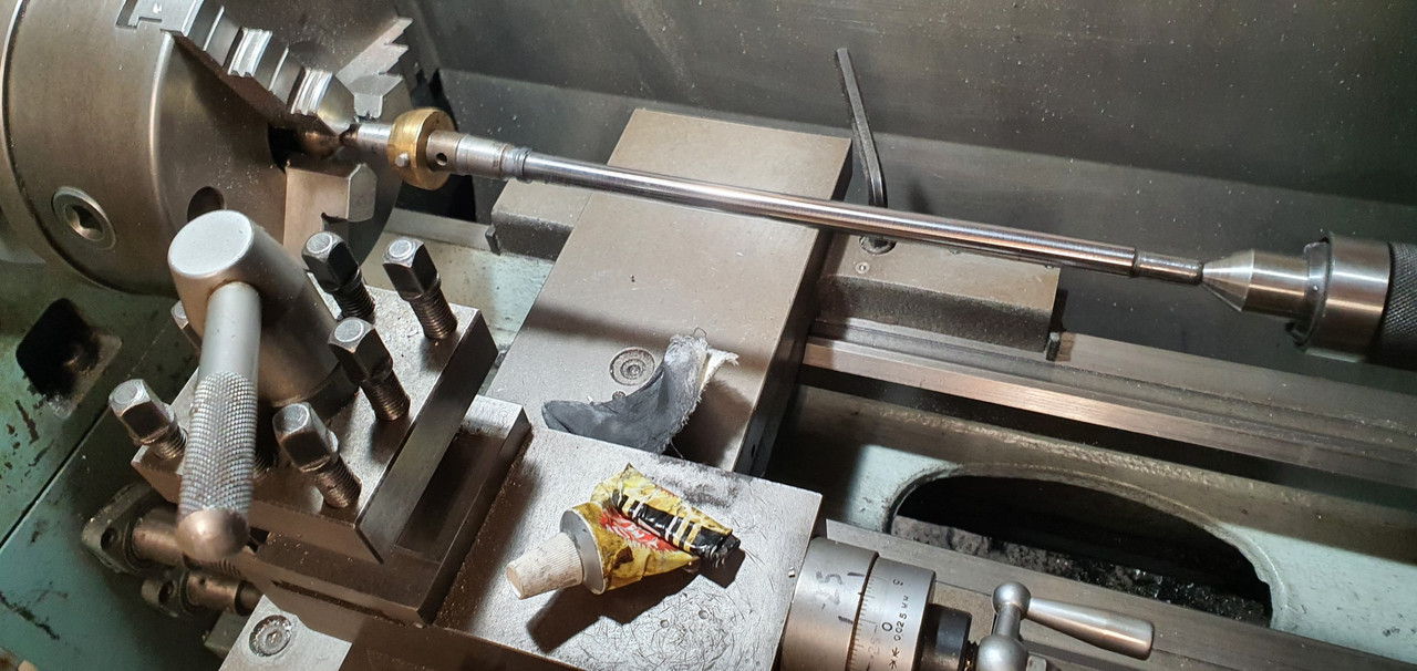
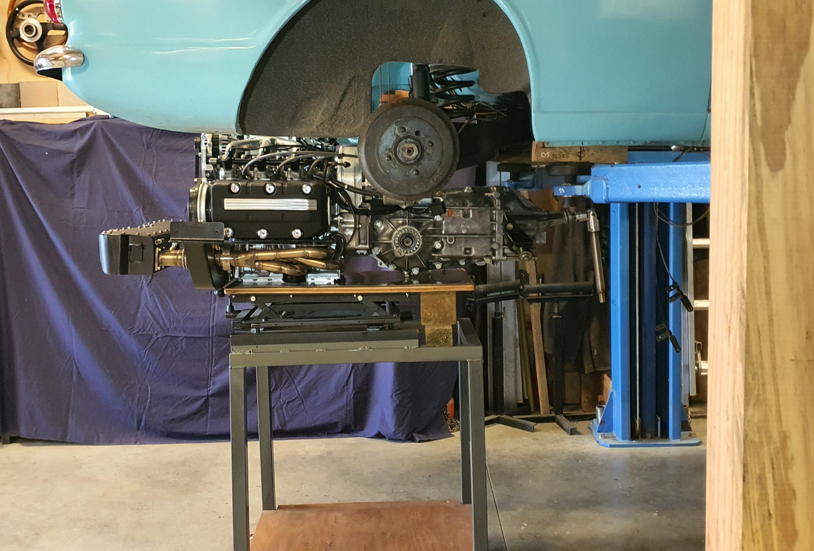
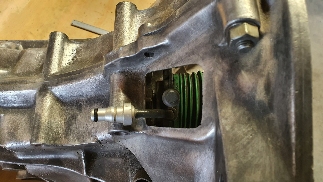
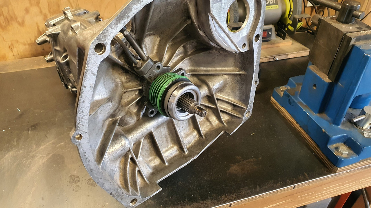
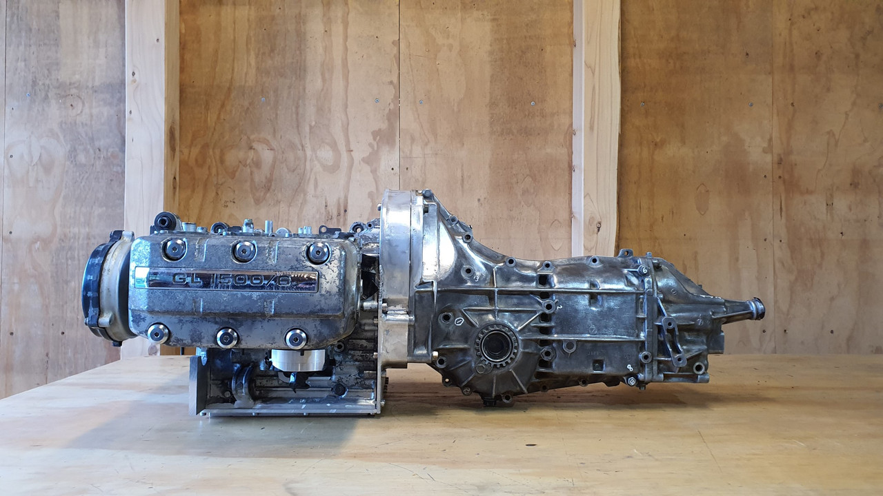
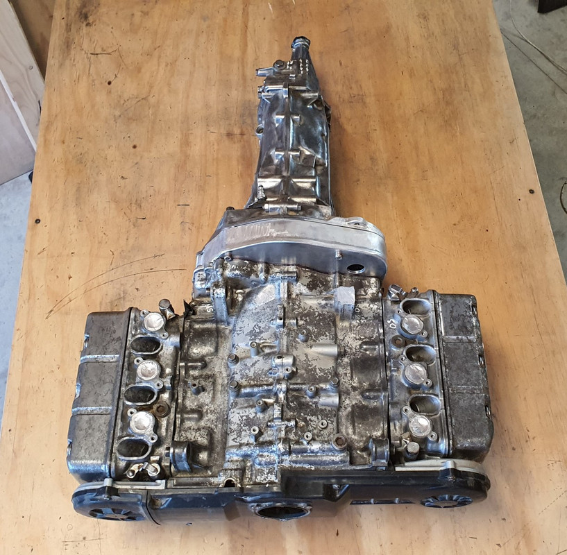
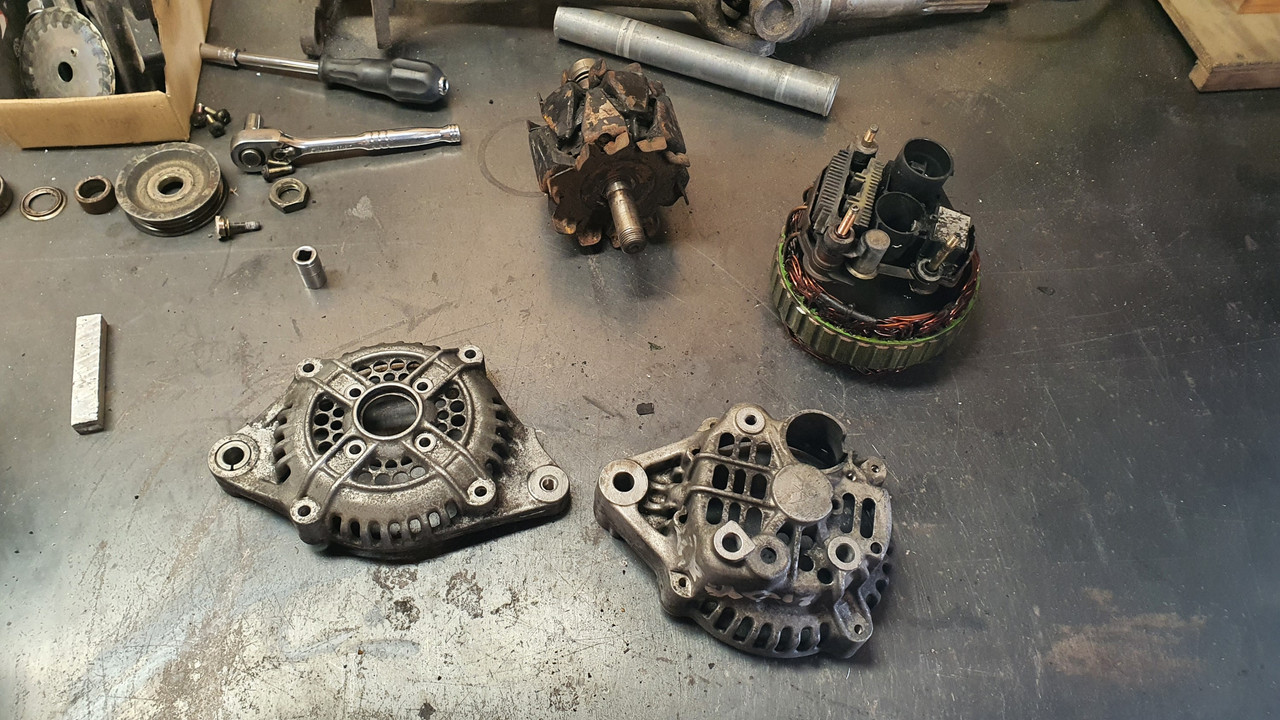
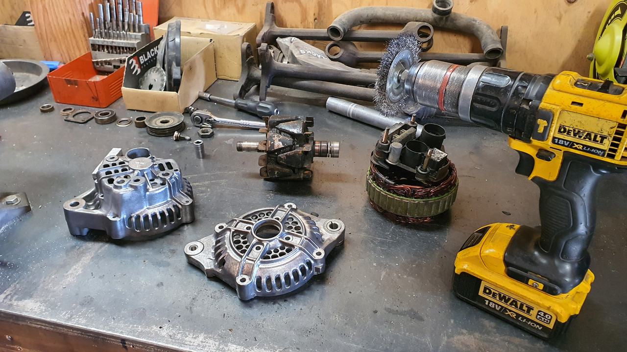
My plan is to remove all of the transmission and most of the drive gears from the casing. I have been looking over my Honda workshop manual and have pretty much nutted out the engineering that I'll need to do . However- before I commit I need to find out a couple of things. I thought I would ask on here and hopefully someone here will have a stripped down engine that they can get me some measurements from.
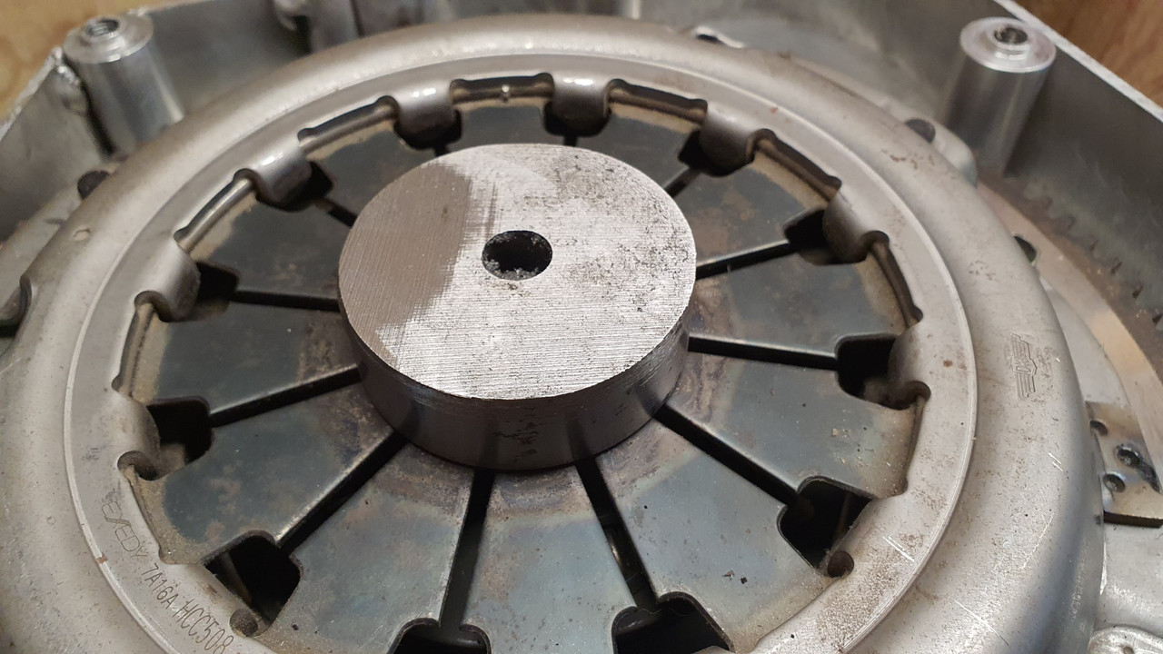
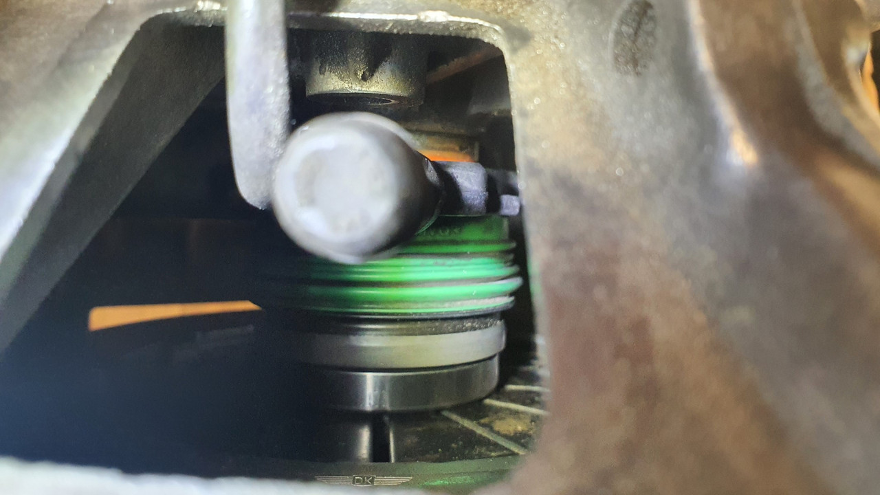
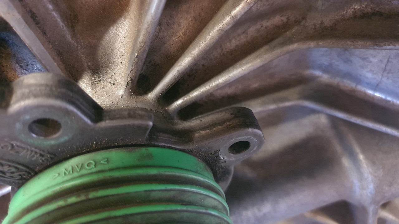
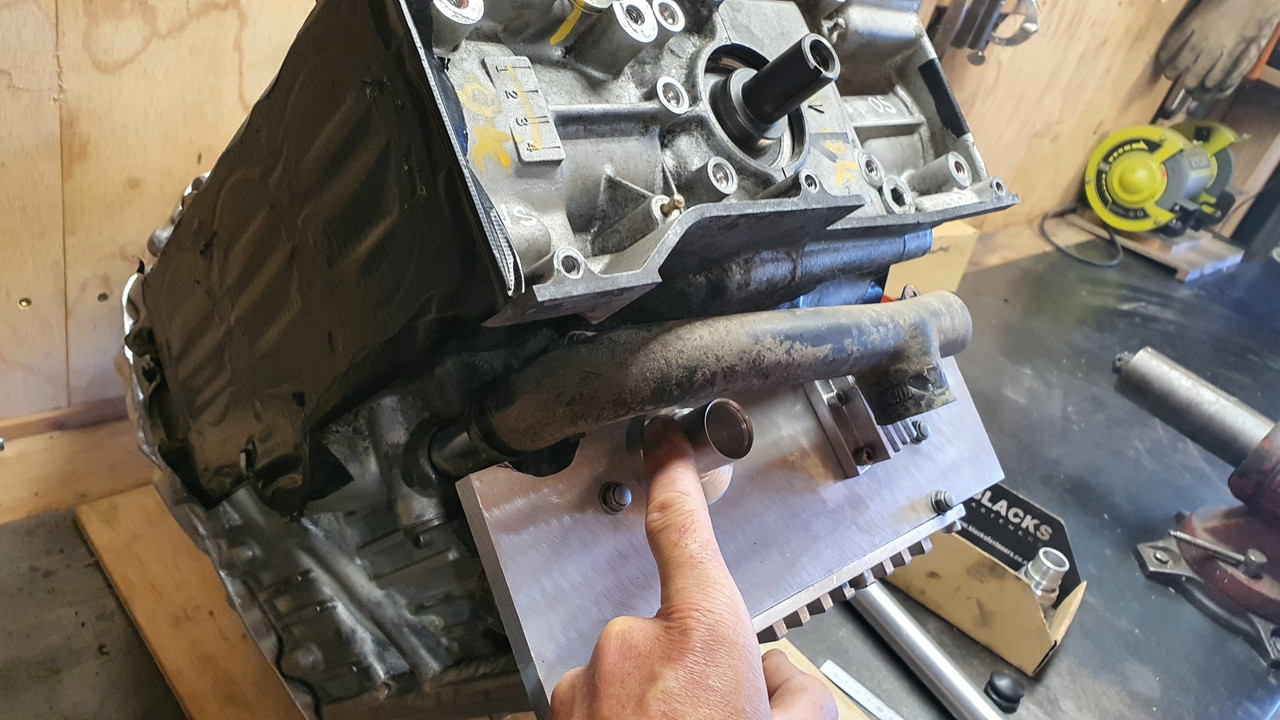
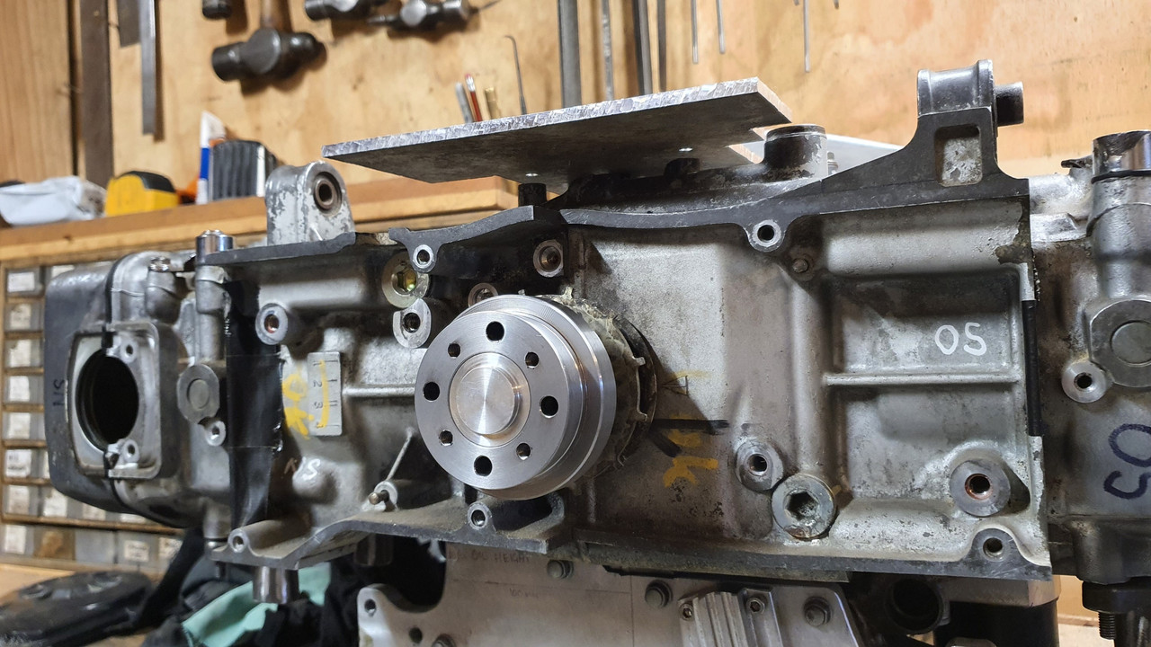
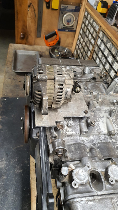
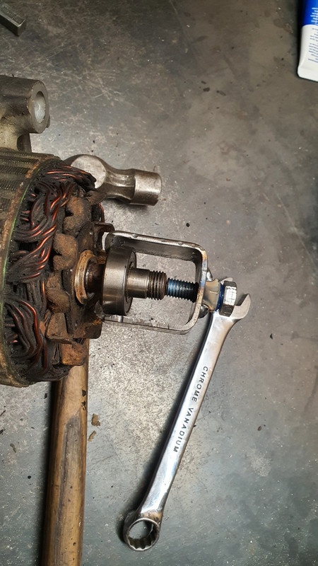
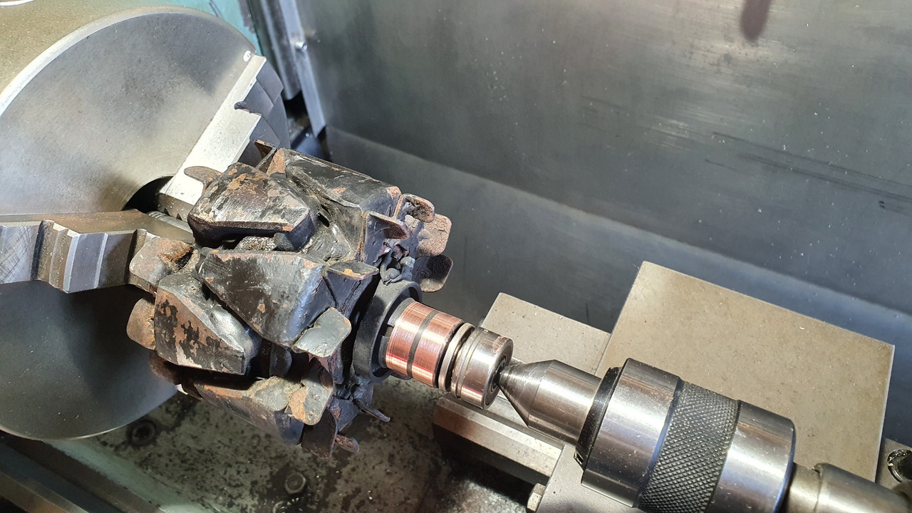
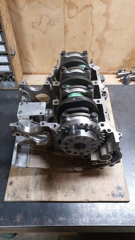
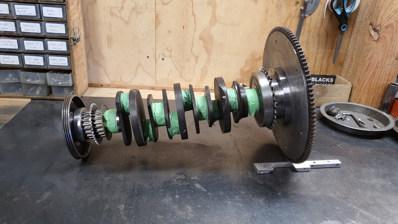
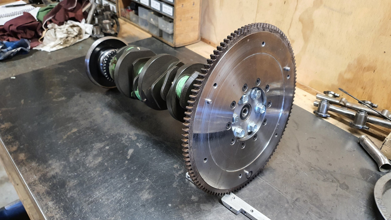
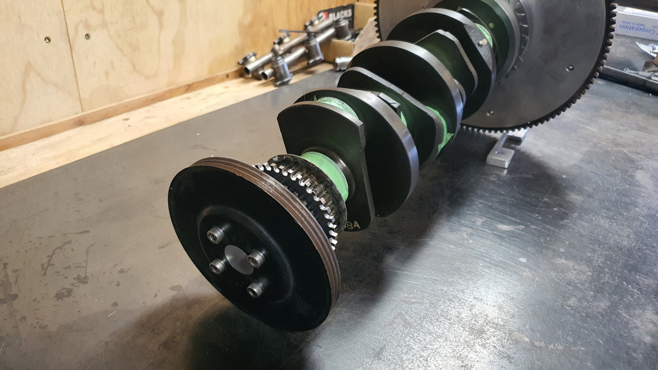
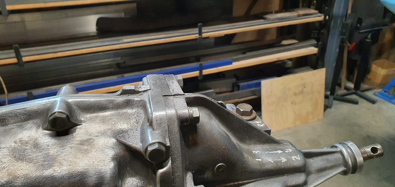
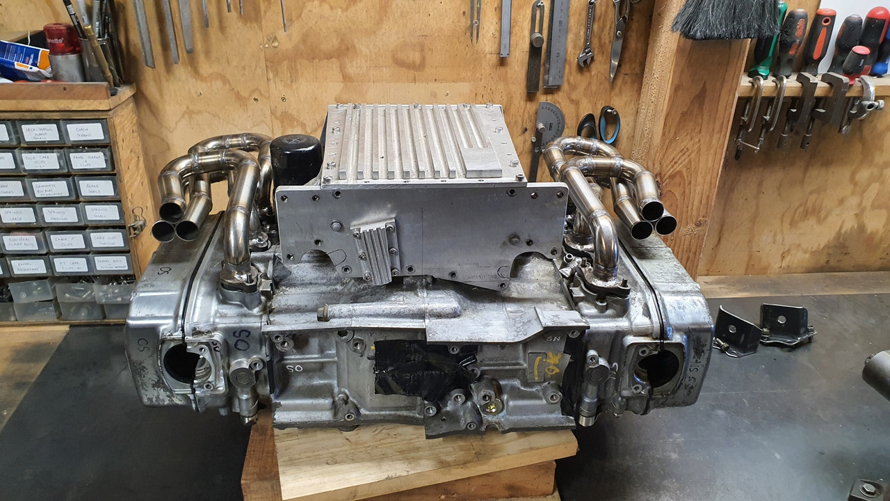
First thing I need to check is the thickness of the flange on the crank that the alternator drive gear bolts to. It takes 6 bolts. Also- what size are the bolts? They look like they could be 10mm? This is all important because I'll be machining a boss to bolt onto this flange and those six bolts will take the loading of a custom flywheel.
Here's a shot of the crank flange I need to know the thickness of...

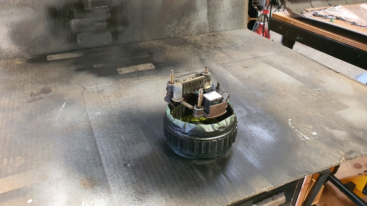
Another question. What is the measurement from the centre of the crank to the bottom of the engine. This is important to work out just how far the sump will hang from the back of my car once installed.
I'll be back soon with more questions I'm sure !
Cheers
alex
Down here in New Zealand I own this little 1965 Hillman Imp that I restored from Feb 2018. I am now looking into the possibilty of fitting a 1990 Honda Goldwing GL1500 engine to potentially build my very own baby 911
This is my Imp...
Here's the Datsun 1200 engine currently fitted...
My plan is to remove all of the transmission and most of the drive gears from the casing. I have been looking over my Honda workshop manual and have pretty much nutted out the engineering that I'll need to do . However- before I commit I need to find out a couple of things. I thought I would ask on here and hopefully someone here will have a stripped down engine that they can get me some measurements from.
First thing I need to check is the thickness of the flange on the crank that the alternator drive gear bolts to. It takes 6 bolts. Also- what size are the bolts? They look like they could be 10mm? This is all important because I'll be machining a boss to bolt onto this flange and those six bolts will take the loading of a custom flywheel.
Here's a shot of the crank flange I need to know the thickness of...
Another question. What is the measurement from the centre of the crank to the bottom of the engine. This is important to work out just how far the sump will hang from the back of my car once installed.
I'll be back soon with more questions I'm sure !
Cheers
alex


.jpg)
.jpg)
.jpg)
.jpg)
.jpg)
.jpg)
.jpg)
.jpg)
.jpg)
.jpg)
.jpg)
.jpg)
.jpg)
.jpg)
.jpg)
.jpg)
.jpg)
.jpg)
.jpg)
.jpg)
.jpg)
")
.jpg)
.jpg)
.jpg)
.jpg)
.jpg)
.jpg)
.jpg)
.jpg)
.jpg)
.jpg)
.jpg)
.jpg)
.jpg)


.jpg)
.jpg)
.jpg)
.jpg)
.jpg)
.jpg)
.jpg)
.jpg)
.jpg)
.jpg)
.jpg)


.jpg)
.jpg)
.jpg)
.jpg)
.jpg)
.jpg)
.jpg)
.jpg)
.jpg)
.jpg)
.jpg)

.jpg)
.jpg)
.jpg)
.jpg)
.jpg)
.jpg)
.jpg)
.jpg)
.jpg)
.jpg)
.jpg)
.jpg)


.jpg)
.jpg)
.jpg)
.jpg)
.jpg)
.jpg)
.jpg)
.jpg)
.jpg)

.jpg)
.jpg)
.jpg)
.jpg)
.jpg)
.jpg)
.jpg)
.jpg)
.jpg)
.jpg)
.jpg)
.jpg)
.jpg)
.jpg)
.jpg)
_(1).jpg)
.jpg)
.jpg)
.jpg)
.jpg)
.jpg)
.jpg)
.jpg)
.jpg)
.jpg)
.jpg)
.jpg)
.jpg)
.jpg)
.jpg)


.jpg)
.jpg)
.jpg)
.jpg)
.jpg)
.jpg)
.jpg)
.jpg)
.jpg)
.jpg)
.jpg)
.jpg)
.jpg)
.jpg)
.jpg)
.jpg)
.jpg)
.jpg)
.jpg)
.jpg)


.jpg)
.jpg)
.jpg)
.jpg)
.jpg)


_(Custom).jpg)
.jpg)
.jpg)
.jpg)
.jpg)
.jpg)
.jpg)
.jpg)
.jpg)
.jpg)
.jpg)
.jpg)
.jpg)
.jpg)
.jpg)
.jpg)
.jpg)
")


.jpg)
.jpg)
.jpg)
.jpg)
.jpg)
.jpg)
.jpg)