Steve Saunders Goldwing Forums banner
521 - 540 of 543 Posts
Discussion starter · #522 ·
We've had a fair amount of rainy weather recently. Last weekend we had a big atmospheric river and got 320mm over 36 hours. Lots of local flooding and quite a few unlucky souls have lost quite a lot. For us it was just some of our driveway getting washed downhill and a few trees coming down so mustn't grumble.

Anyway- it was a good excuse to stay indoors, crank the fireplace, music, espresso machine and tinker with the Imp.

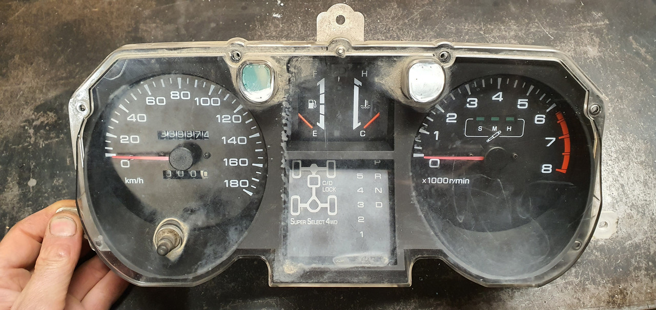
Ages ago I had picked up these Mitsubishi V6 pajaro instruments from the wreckers..


In previous posts I had stripped them down, chopped off all the excess bits not needed (trip meter etc) so they'd fit into some housings I machined out of thick walled alloy tube. I had found a Toyota speed sensor that I adapted to fit my Subaru transmission. Wired them up and checked it worked, which it did well but it was reading a good 10 ~ 15kph out. I then packed the lot away in a box and stashed it away.

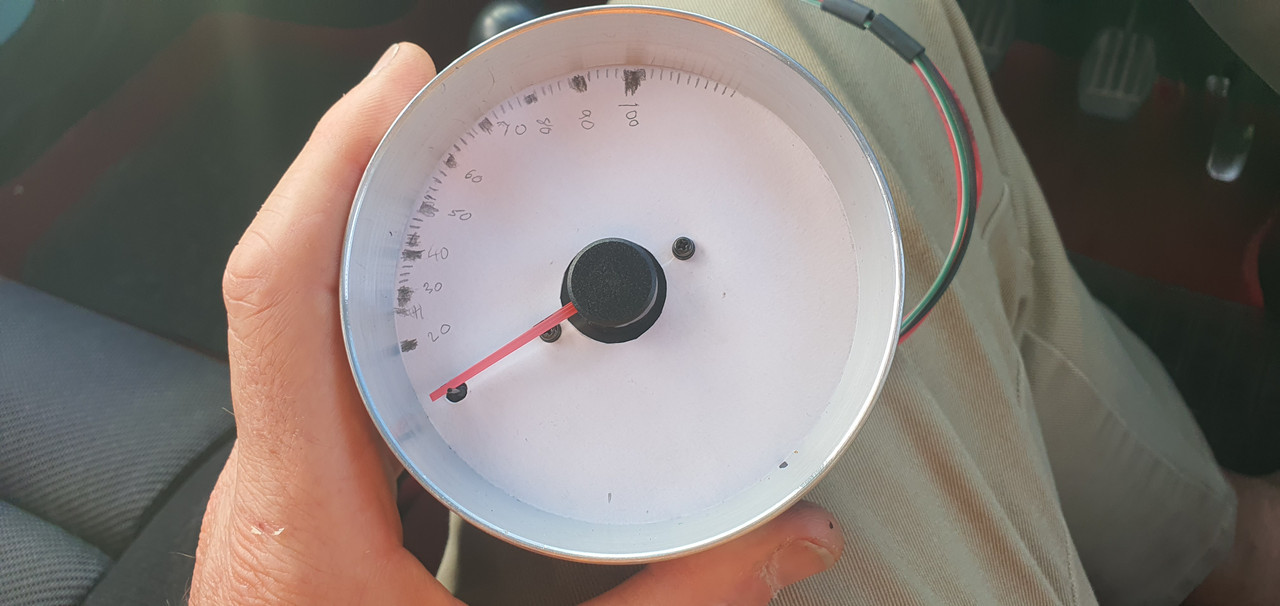
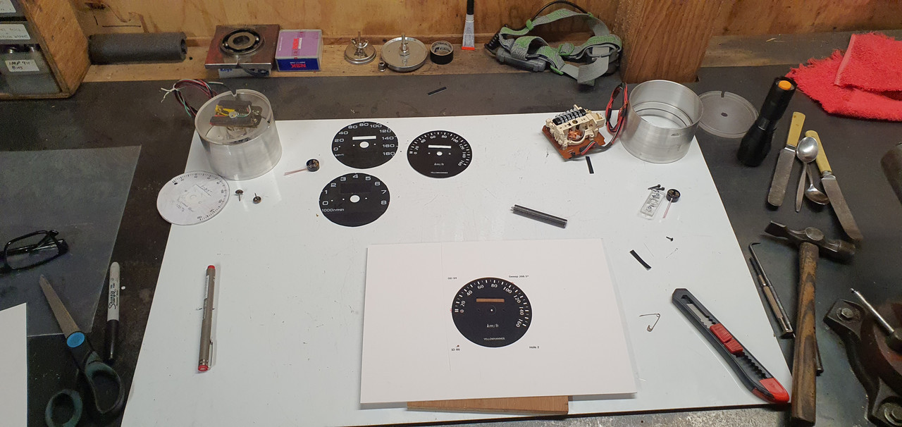
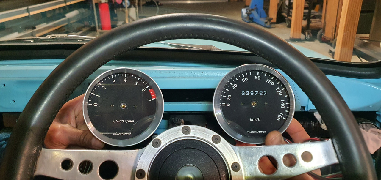
It was time to crack on and make something of them. First job was to work out an accurate speedo face to suit the setup. I cut a circle of paper, fit it in place and we went driving. Using a GPS speedo we marked out all the various speed points.


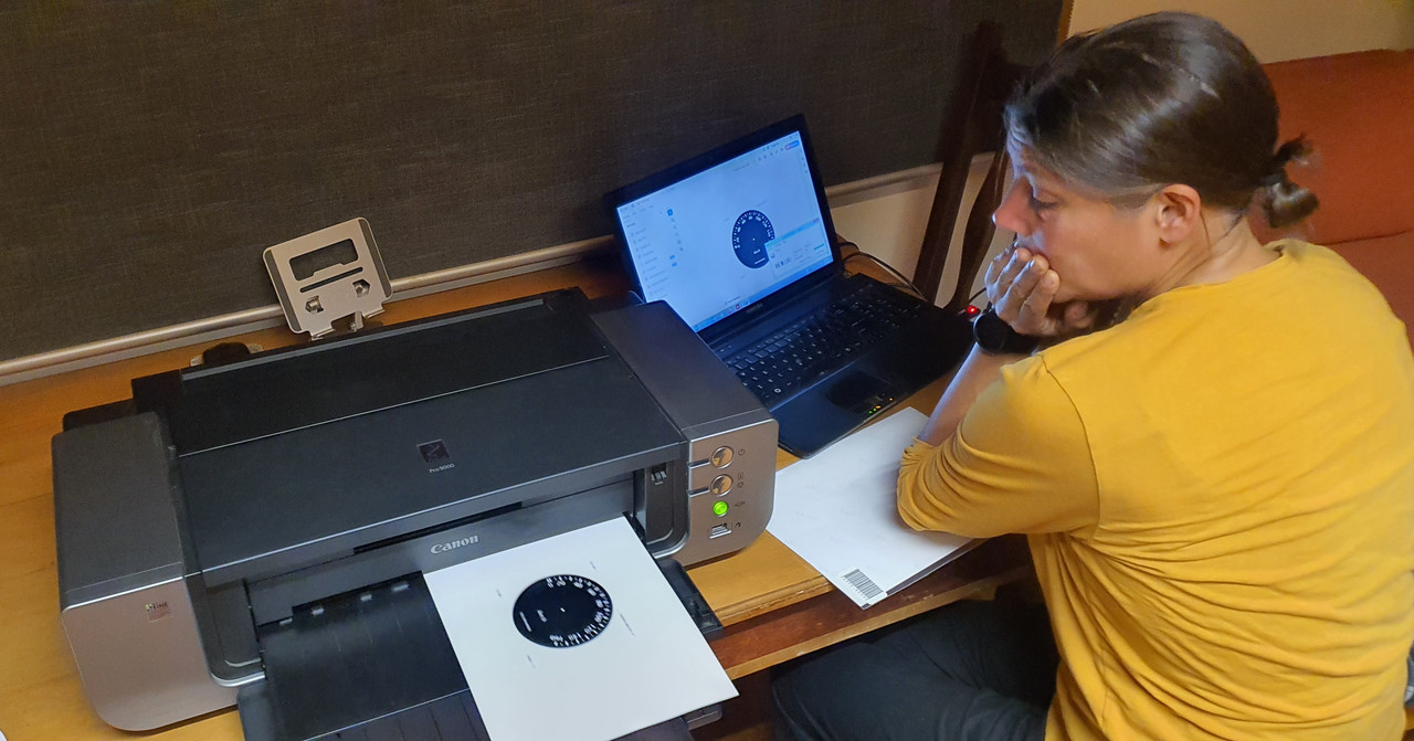
Then I used a program online...


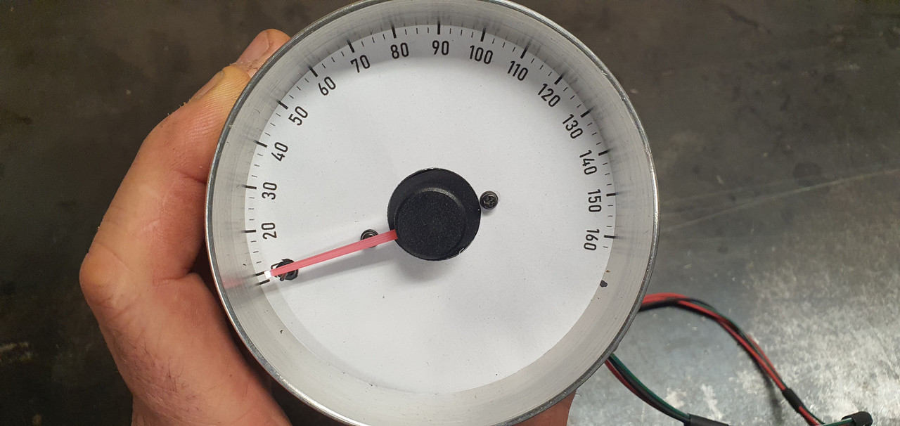
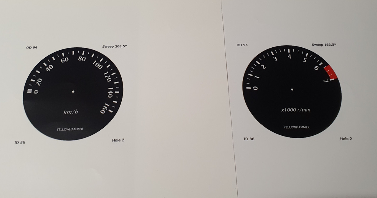
..however it didn't create what I wanted as most speedos have non linear markings, especially 0-20. I chatted to the fella who was running the website and he added some custom bins into the program to suit and it worked great. We printed off a new face that matched the hand drawn one and went for a drive to check it was good..


Then I spent some time having fun creating some gauge faces. I had a particular style in mind. My current design turned out pretty boring given how far one could go with the variety of fonts, colours, images, text but I wanted a 60s/70s look to suit the car and dash layout I have in mind. Fun thing is I can change it easily now I have a saved accurate template.

Used the big printer we have that barely gets used.


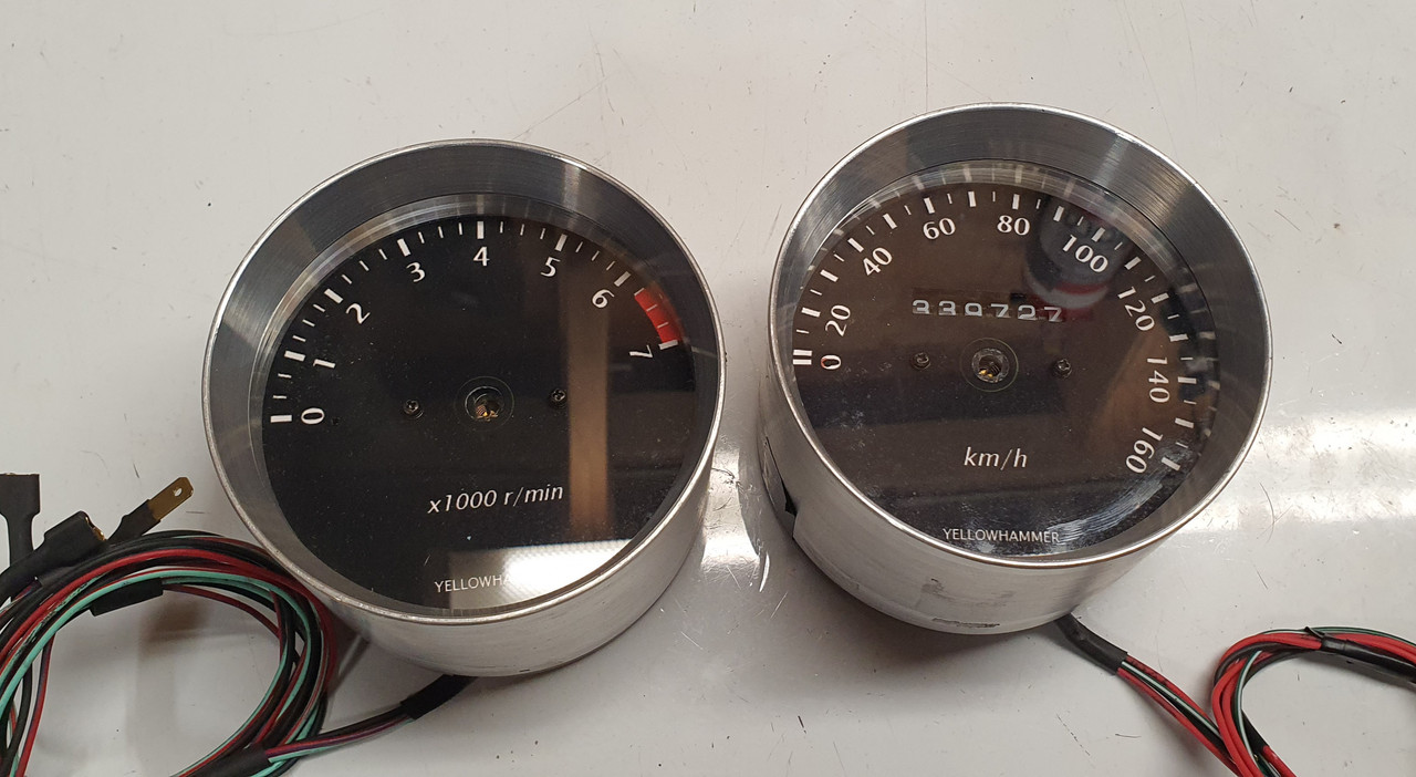
Cut them out to suit. Machined up some tiny wad punches to do the holes.


Into the housings.


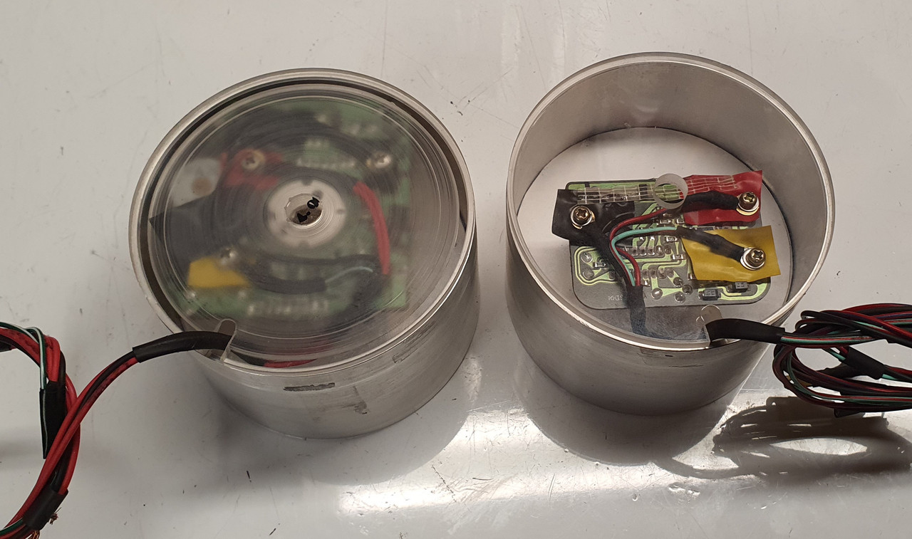
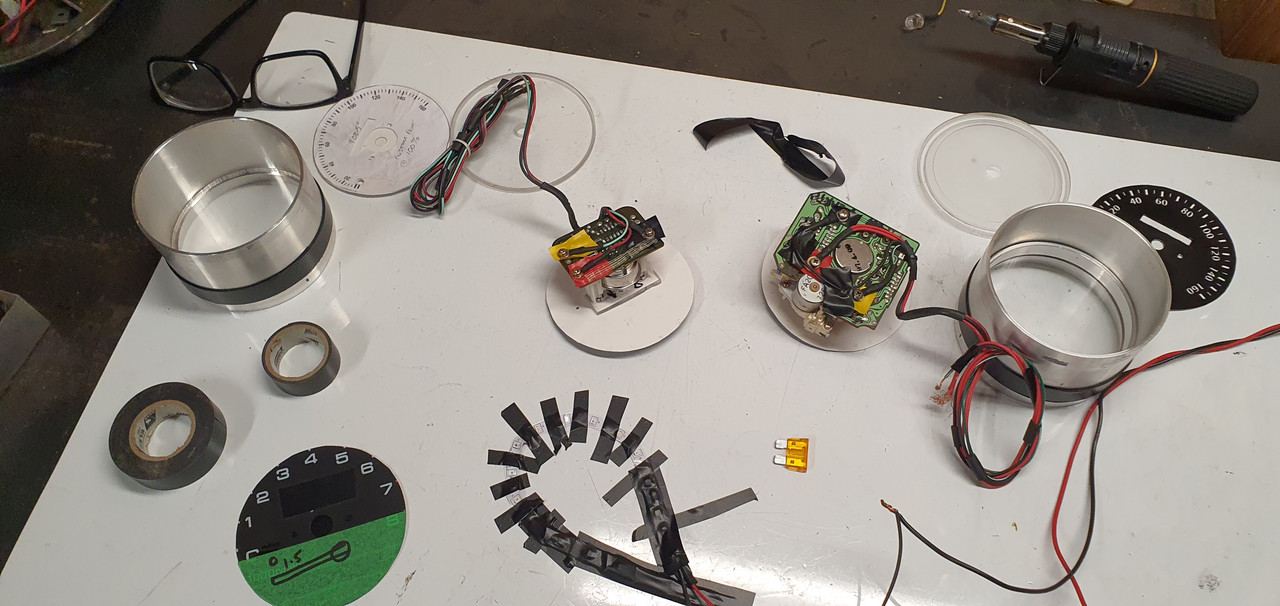
The backside. Later on I'll need to add some led lights to shine through the white font.I'll also re-set the odometer to match the current reading even though it'll be in km from now on. The needles will then go back in place once I have finished all this.


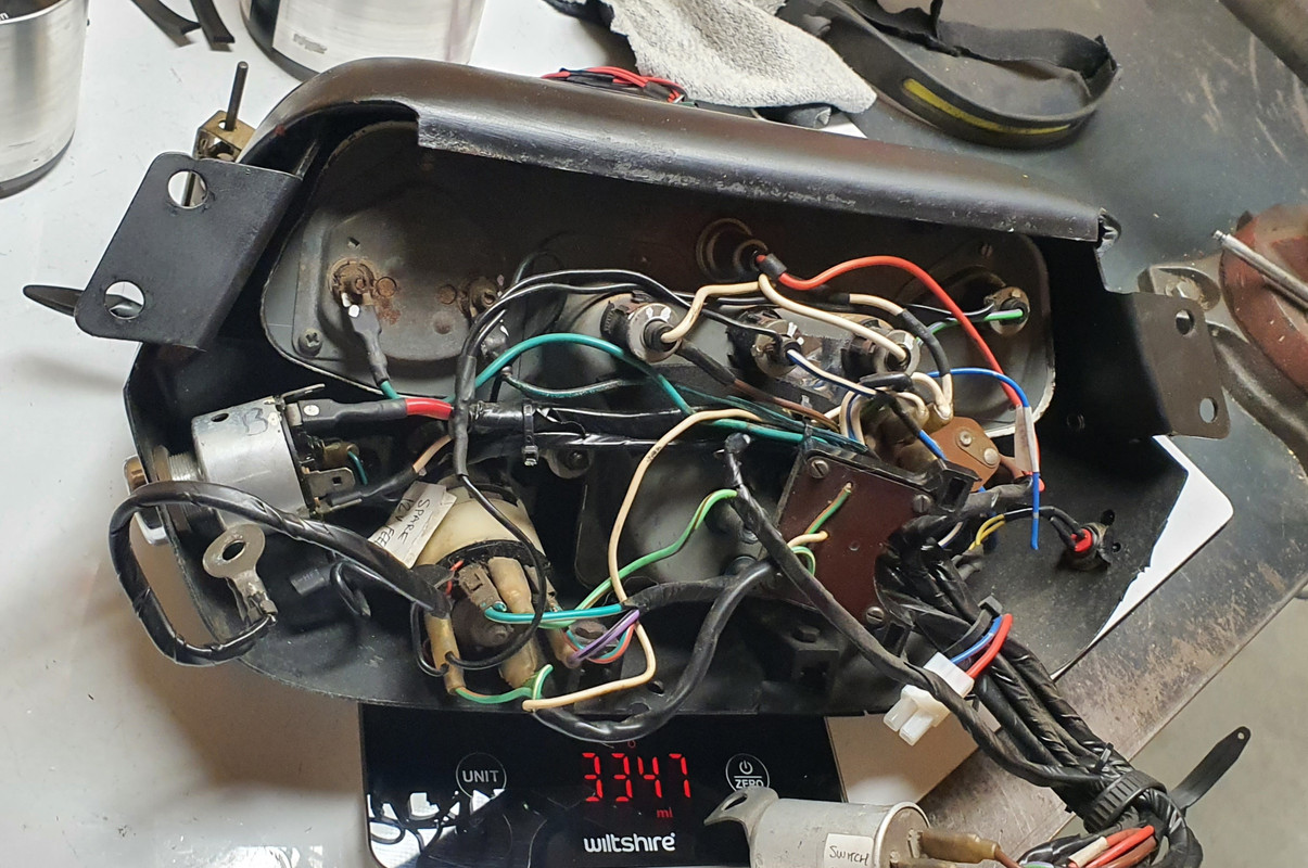
I removed the original Imp dash pads and instrument cluster. Its a heavy bit of kit. Comical wiring layout too.


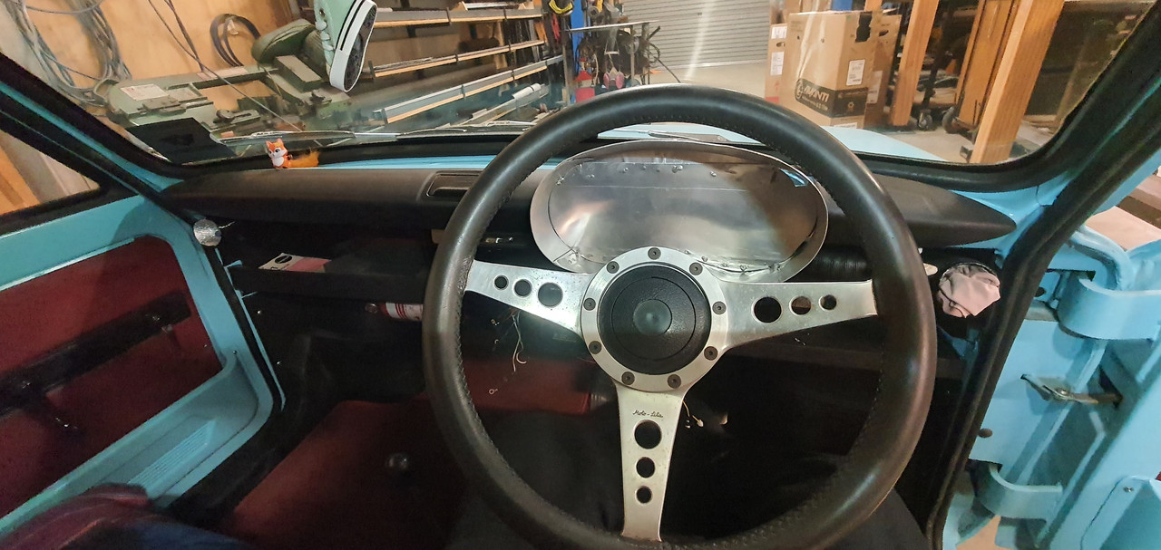
Sat in the car and eyed up how I'd like the gauges to sit. The idea is to build a pod that will work with the original MK1 Imp dash pads which I really do like the style of.


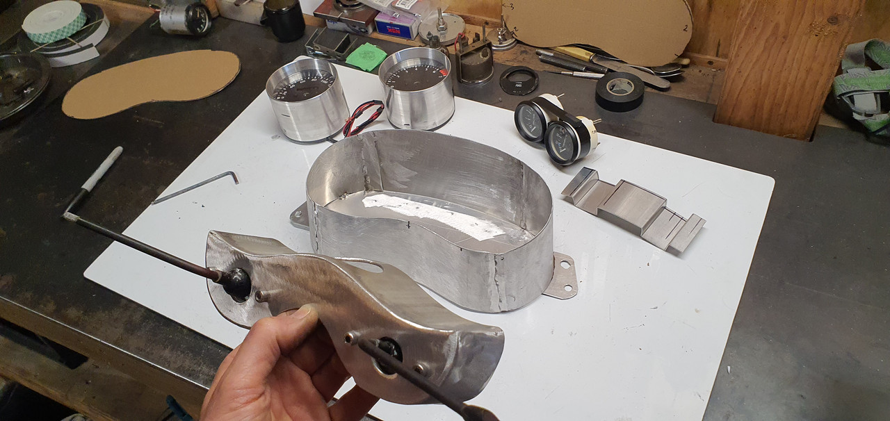
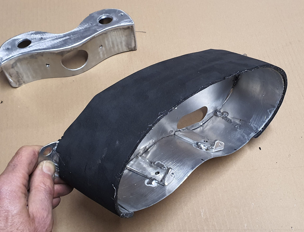
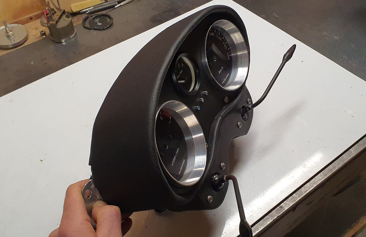
I had part sheet of 1.2mm alloy which I cut, bent, rolled, twisted and tweaked to shape, welding all the bits together doing my very best to try not to create holes. Not the easiest thickness alloy to tig weld but managed ok. I also welded up a bolt on pod that sits below to take the original Imp indicator stalks.


Checked it was ok.


Covered the outside in medium density foam..


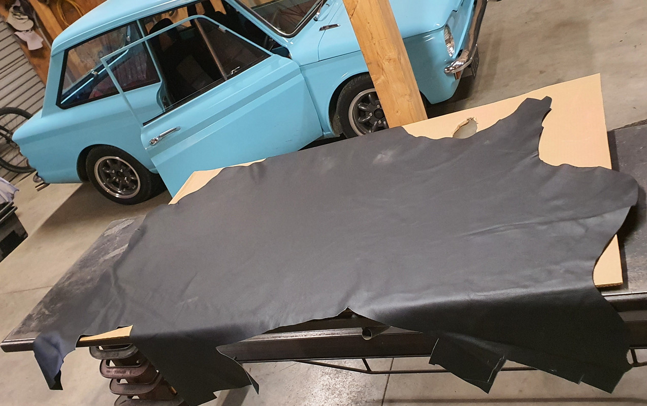
Bought some more cow that local canvas place still had a stash of..


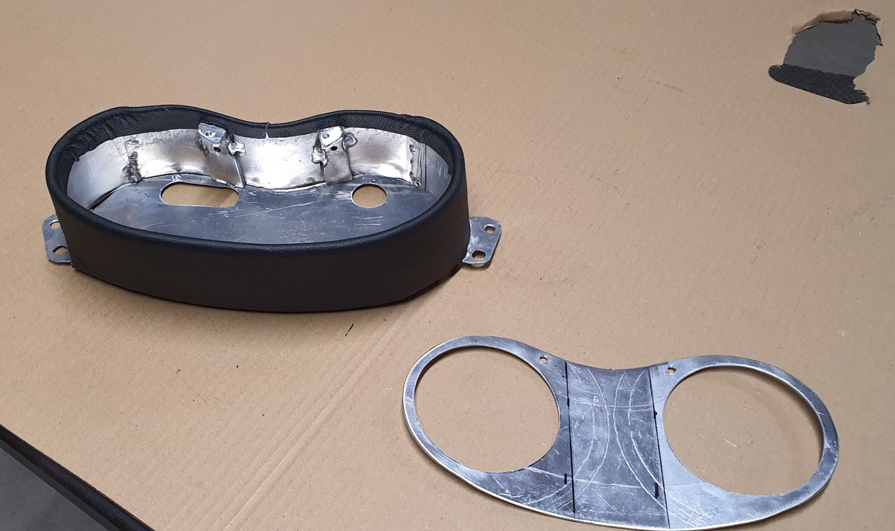
Very carefully cut and glued it in place.


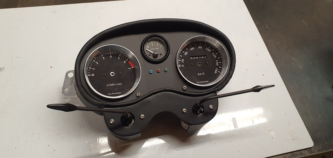
Painted the other alloy parts in etch primer then satin black. Added some tiny warning lamps. Most important gauge, the oil pressure gauge, resides in the middle..


Really happy with the finish. There's a couple of blemishes (tiny knife nick) but overall considering the awkwardness of this build I'm stoked.


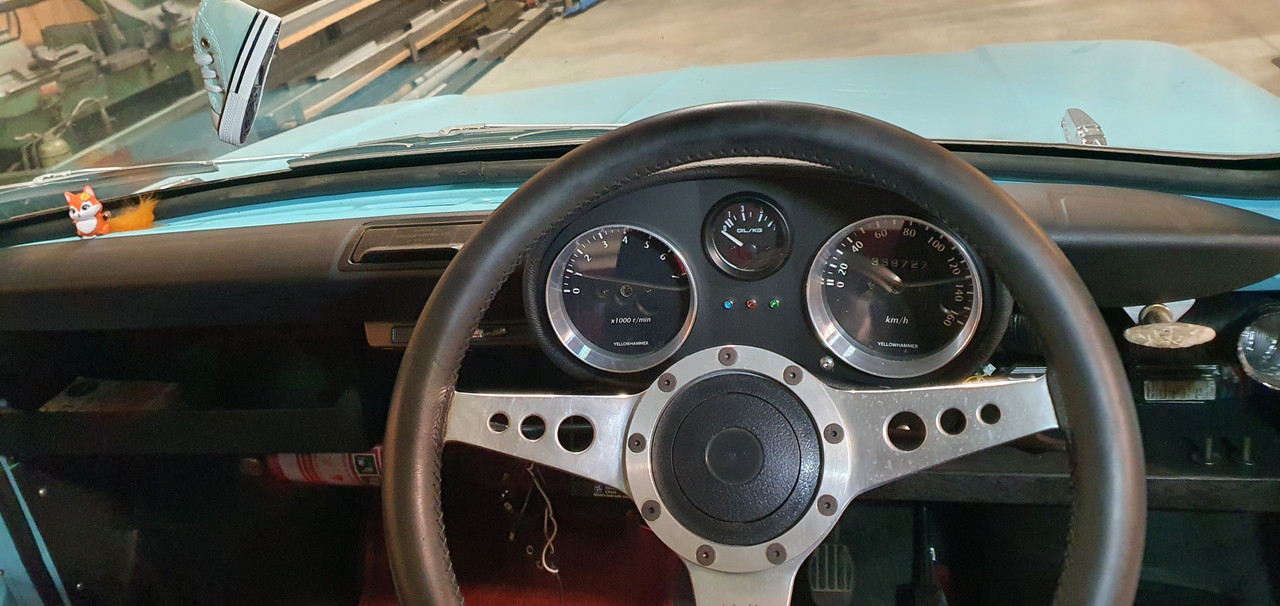
And bolted in place. I can adjust the angles of the gauges quite easily too but its currently good for both of us.


Ties in really nicely with the dash pads..


Next job is to sort out the wiring. I'd already made it far more user friendly compared to stock by having added several multi plugs. I'm going to re-do it though and use some smaller wire where I can along with Deutsch plugs. There will be a new dash face below the dash pads that will house 3 gauges, some rocker switches and a Triumph eyeball vent at each end.
 
No one doing a conversion like this is well; however, it is a moral imperative. Proves we are still higher on the food chain. I would like to have his workshop. Cheers
 
Yoeddynz,

that is the most descriptive, and cleanest post I have seen yet.

I am amazed at how you can manage to put so many images inside a post, and do it perfectly.

and yet, you still have that confounded steering wheel on the "wrong side" of the car :giggle:

as for youTube videos, I watch a few channels where the Masters that be, are making Millions of Dollars a year from their channels....

One guy has over 3.5 million subscribers, the other guy has over 4.5 million subscribers, he owns a drag strip, and airport tens of dozens of race cars, and just built a humongous airplane hanger and house side by side, on his newly purchased airport in southern Florida.

Cleetus MacFarland... Cleetus McFarland
 
Discussion starter · #529 ·
Hey flellas. I just woke up and checked in on the thread. Thanks so much for the positive comments :) I've been told by quite a few folk that I should do more youtube posts. I'm just never sure how to go about it as I'm not that confident that I'd be very good in front of a camera. I'd also be worried I'd run out of content. I really should have started something waaaaaaaaay back when I started this project :ROFLMAO:

But I do love watching other people's channels.
 
Question regarding your ignition timing table. I noticed that it is very defined using decimal points. TS for Speeduino doesn't allow the spark table to be as detailed; however, it accepts decimal points and shows the value rounded up or down, checked using 15.3, displays as 15, and 15.8 displays as 16. Have to keep additional notes to keep up with the ignition timing values.

Did you use a program/app to get that specific ignition timing table? I have noticed that TS for the mega squirt ECU family is different from the Speeduino TS.
 
Discussion starter · #531 ·
Question regarding your ignition timing table.

Did you use a program/app to get that specific ignition timing table?
Sorry for late reply. After my last post we'd left on holiday to the UK and while on our way over our district back home got smited by a big weather event - huuuge account of rain. This on top of an anyway wet previous 2 weeks after the last event. End result is a large amount of flood damage and slips including our own property. We were 'lucky' in that the slips we've had are at the far end of the property and only affect one driveway entrance. Our neighbours house in the valley floor has had food water through it. Many other houses lost.

So it's been a hectic time for us. Not much we can do but look forward to a load of clearing up when we get back. Hence I've not been on the forums.

As for ignition table. I used a third party ignition table generator. You add as much detail you can and it spits out a result you can put into ts. I can't remember the site though but I'm sure it can be found online.
 
Good morning. Sorry to hear about flood issues, water is very unforgiving. Good that you were spared form the worst.

Question: do you use an O2 sensor? Reason for question is that Honda did not use an O2 sensor for the '82 CX500T, '83 CX650T, and '85/'86 GL1200 CFI systems. Second reason for the question is that the GL1200 CFI engine tune uses two SD VE tables. Don't know why but surmise it may be to increase granularity at idle and low powers, and then again at cruising and higher engine power, negating the requirement for an O2 sensor. I would expect an RPM is chosen to switch between the two. Third reason is that the O2 sensor is only installed in one exhaust header for that specific side. The only aftermarket ECU that I am aware of that can use two O2 sensors in an engine tune is a MaxxECU from Sweden.

The better the calibration of the VE and ignition advance tables, the less reliance if any on the AFR table. Thoughts?
The early Honda car PGMFI didn't use an O2 sensor either. Same time period.
 
Discussion starter · #534 ·
My Megasquirt ms3x can run two wideband o2 sensors, as can many of the better Link (nz) and Haltech (Australia) ecus. I've not bothered because there's little to gain on a fairly standard tune engine which I know is in good low mileage condition that's running a single throttle body. If I was chasing bigger power and using itbs I'd probably run two sensors.

I'm running closed loop control my system needs the extra info from the wideband and will adjust the fuel table on the fly to match what I've set as my ideal afr table. On my last install, the ms2 controlled mazda V6 in my old viva I was running open loop, batch injection and it definitely wasn't as smooth at idle or just off idle. I also attribute the exceptional economy ive been seeing from this flat six to the full sequential setup I'm running. Exciting too because I know it can be tuned to an even better state in time 😃
 
Discussion starter · #535 ·
Big post alert :)

Hannah and I have come back from a lovely 6 week holiday, based mainly in Oxford, UK. Mainly cycling and catching up with Hannahs family. We actually got some really good hot, sunny weather too!

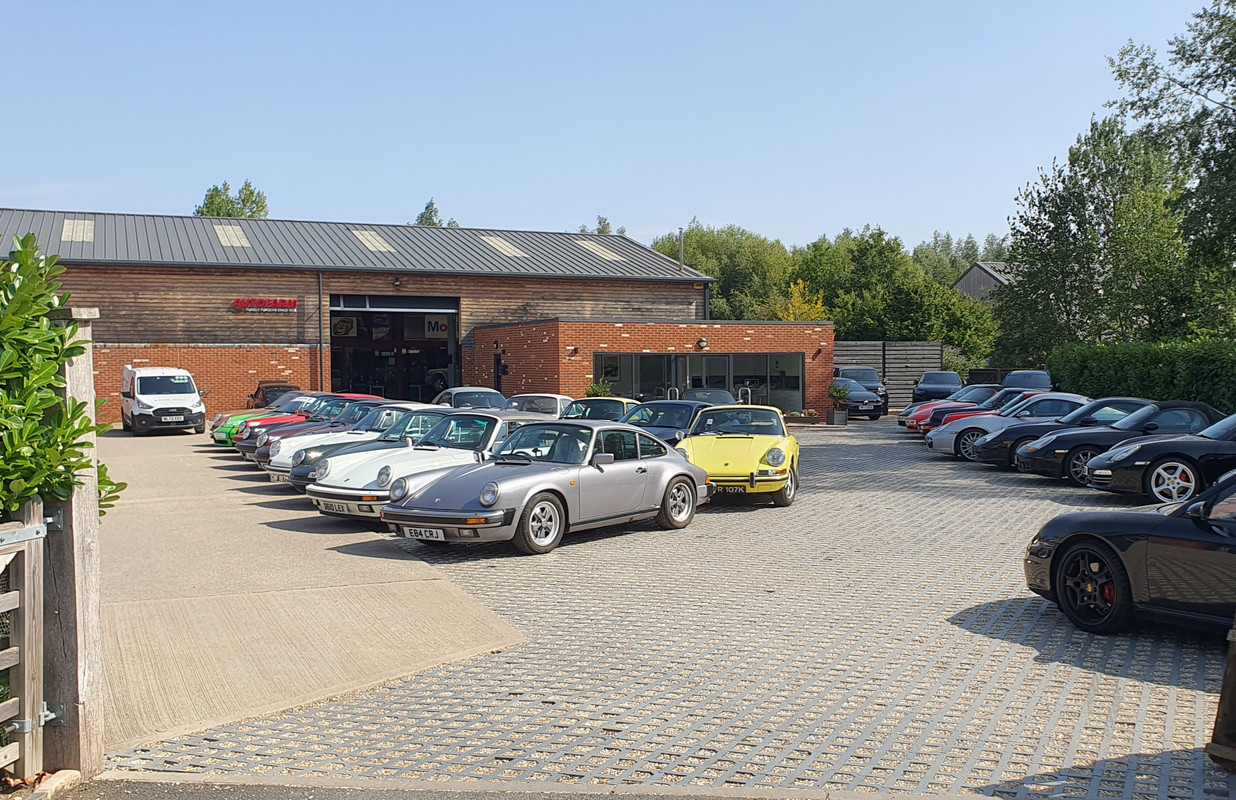
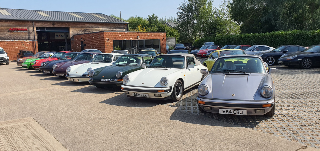
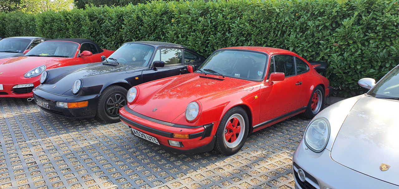
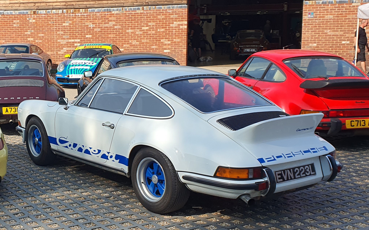
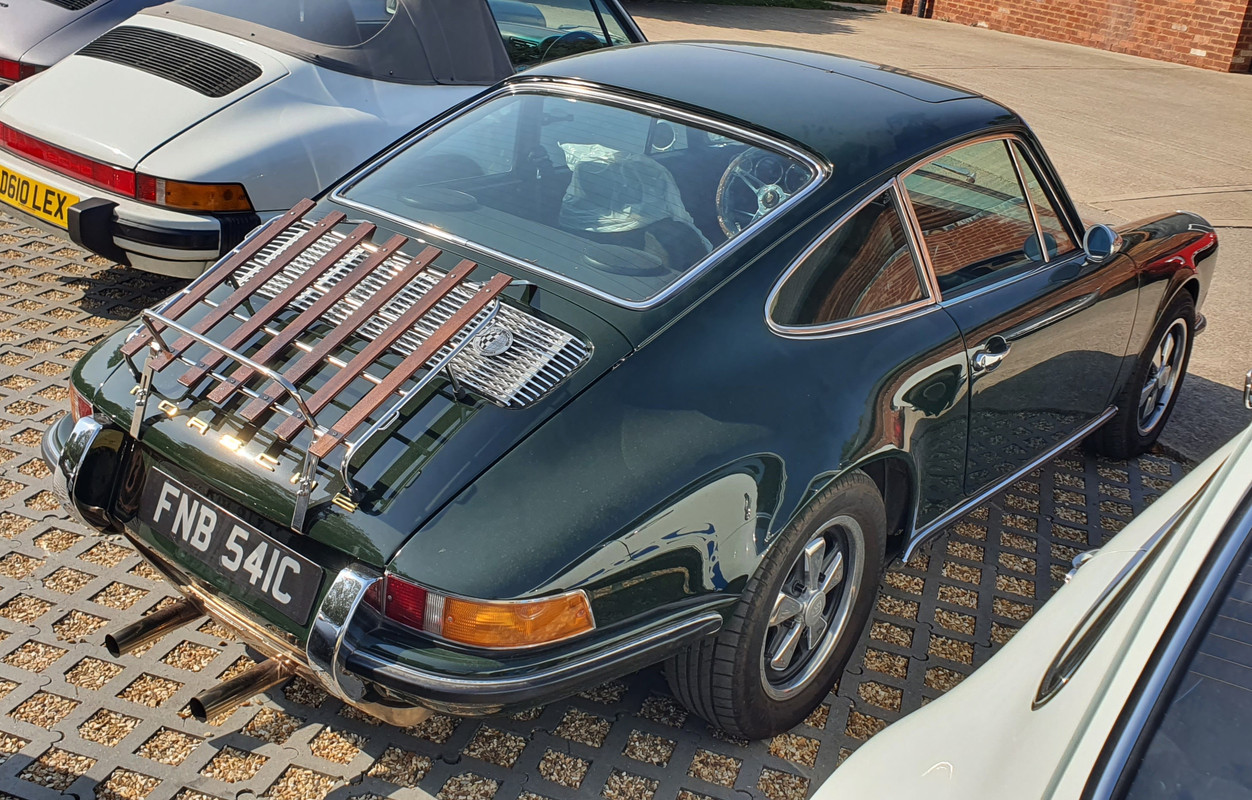
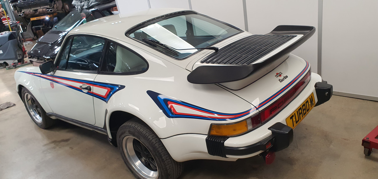
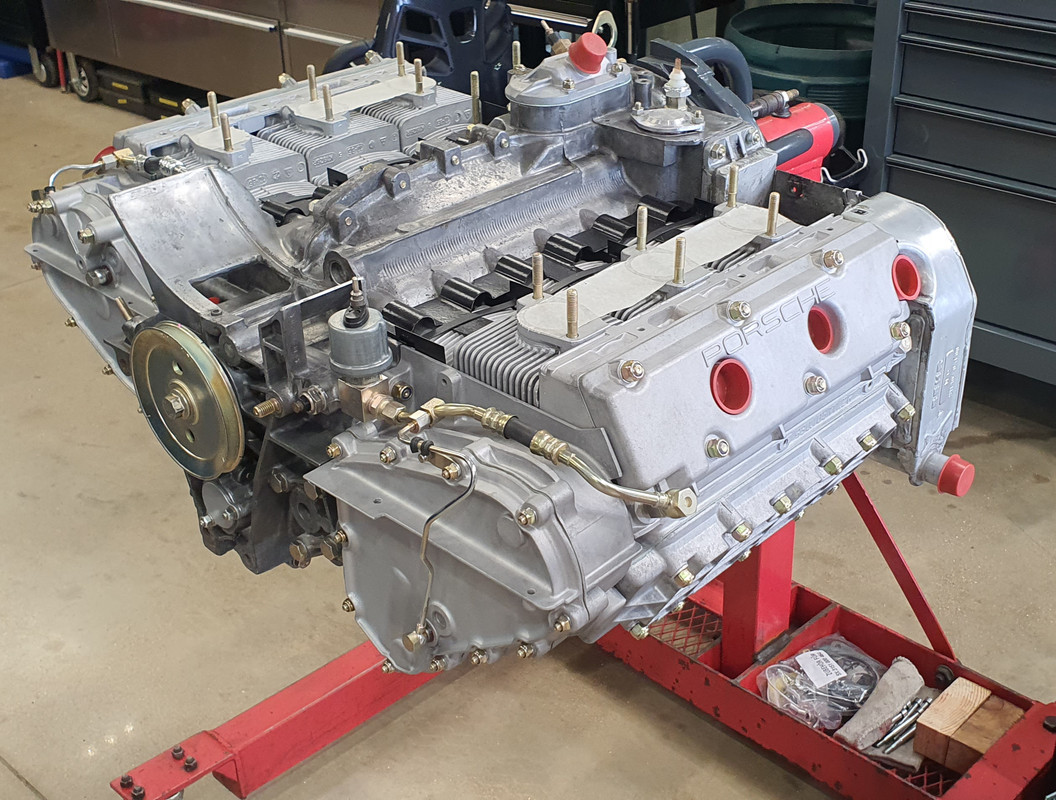
While there I contacted a local to Oxford classic Porsche workshop. I took a train 10 miles north to Bicester and walked from there. What was meant to be a short walk turned into a 20km walk in the sun on a 34 degree day thanks to me following out of date Google maps. Lessons learned that day. But I got there in the end and had a tour around the place. Very friendly staff, very tidy. Some fantastic 911s inc I think at least 3 genuine Carrera RS 2.7s. I took many photos...


So that was nice.

They are looking for some staff including a metal worker/engineer for the restoration side. If I was still living in Oxford I probably be there in a flash for the experience.

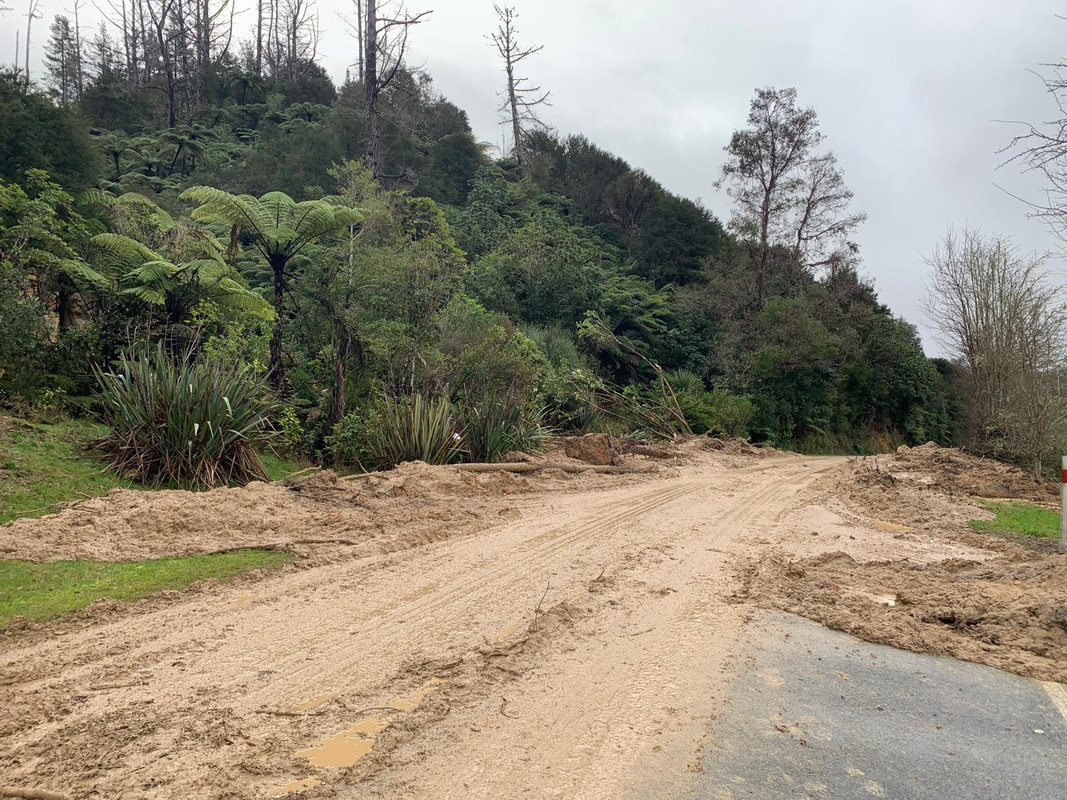
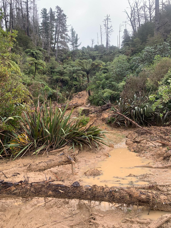
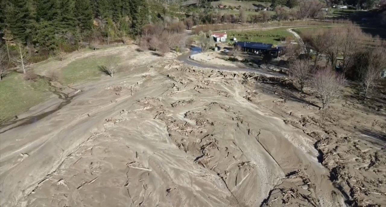
But back to NZ and we were welcomed with a whole load of slip clearing to do. Our place was one of the many local properties to get completely battered by a massive rain event that happened while Hannah and I were on our flight to the UK. Absolute carnage. I'll do a more detailed update on our bushblock thread.

This is one of our driveway entrances..


The neighbours place got silt through their house..


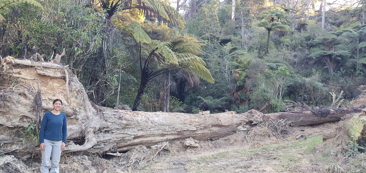
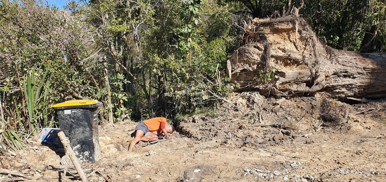
Fun times. We've got a lot of clearing to do yet including dealing with this huge tree which floated down on a wave of mud and stopped 3 metres shy of our mailbox..


We spent the first week back home fixing our water system which was damaged..


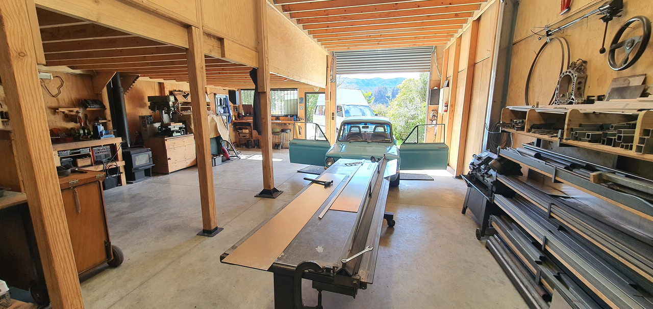
Anyway - that's that. It could have been much worse. Others local to us have lost their houses. Luckily our workshop was fine.

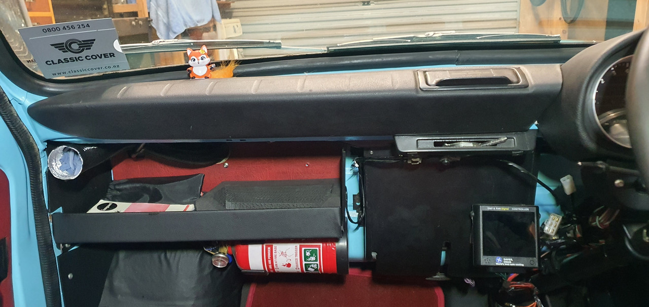
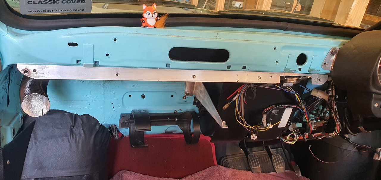
Back to the Imp. My last post was the speedo and rev counter instrument pod build. Next on the list was a new dash which was to include revised switch gear, the other gauges, a pair of Triumph 2500 eyeball vents and an actual glove box rather than this shelf layout as on the passenger side...


and drivers side..

 
Discussion starter · #536 ·
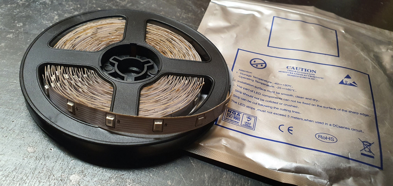
But before making a dash top I needed to sort out lights on my new instruments. I had some rolls of ali express multi coloured led strips.


Stuck them on the bench and had a play..


Cool..


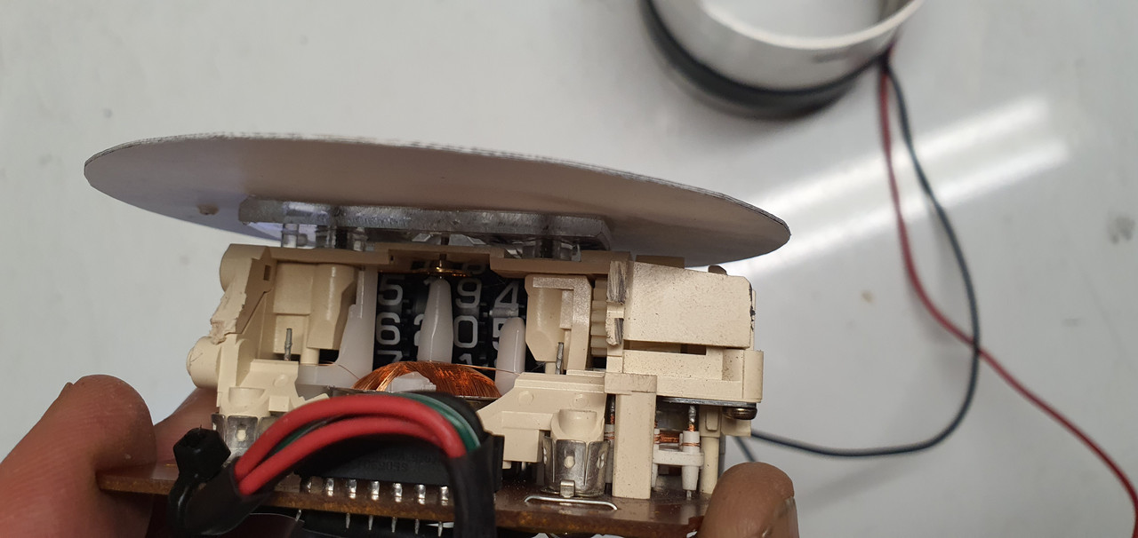
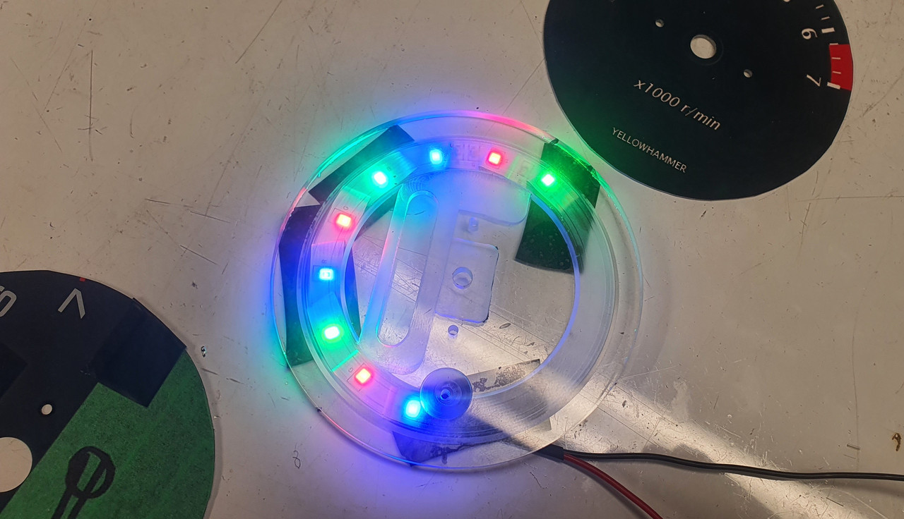
I had to work out how to hold them in position and disperse the light. You can see here the thin bit of molded clear plastic backing from behind the gauge faces had been cut down when I built them.


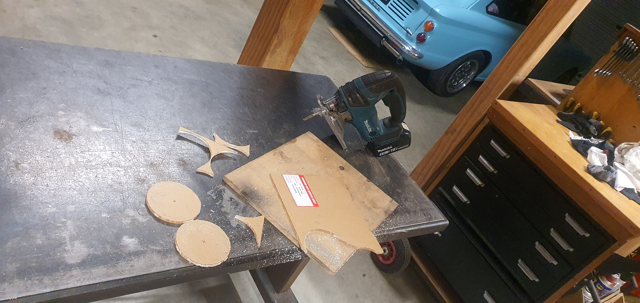
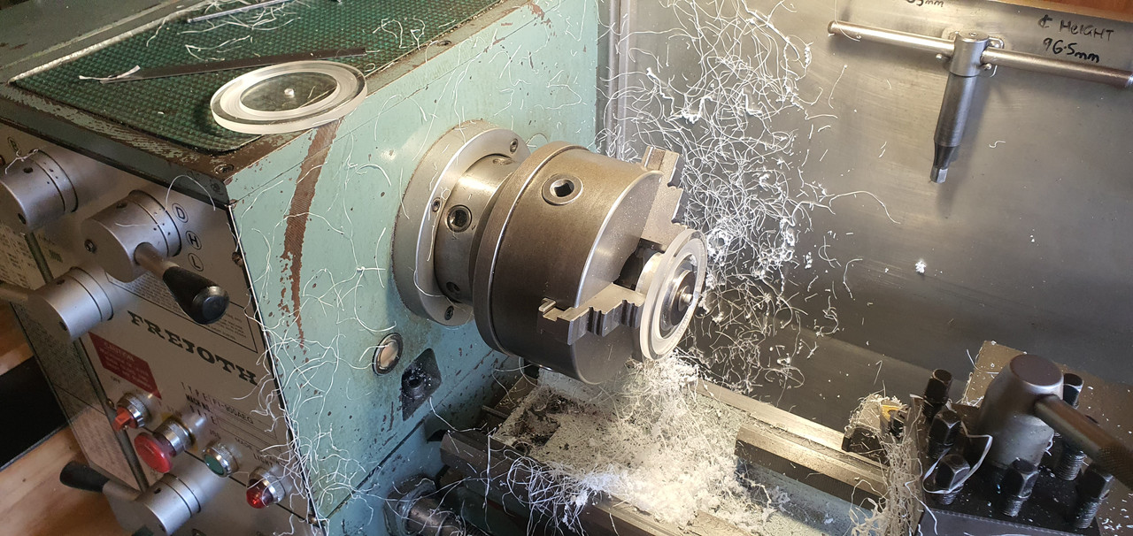
I cut some more acrylic discs..


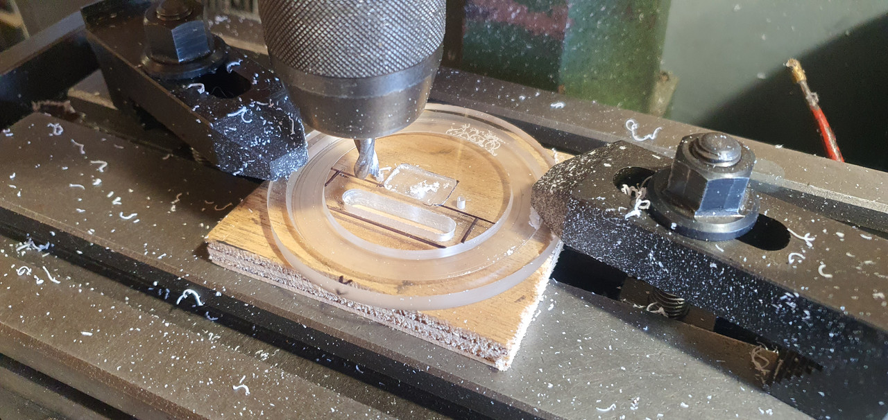
Made lots of mess in the lathe and mill..


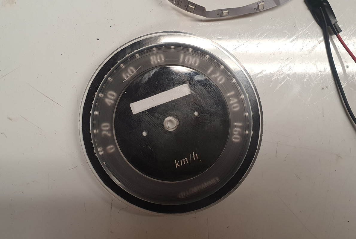
Leds sit in the groove..


Softens and spreads the light and diverts some light to the pickups on the needle centres.


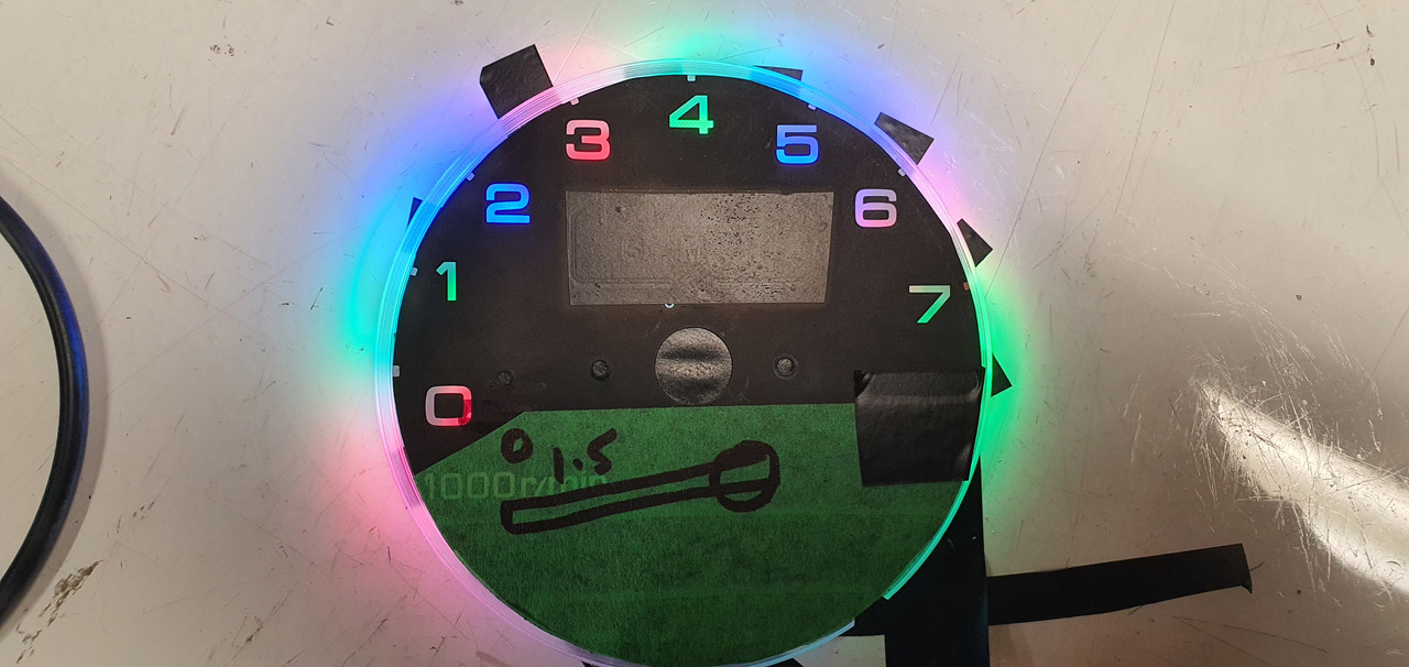
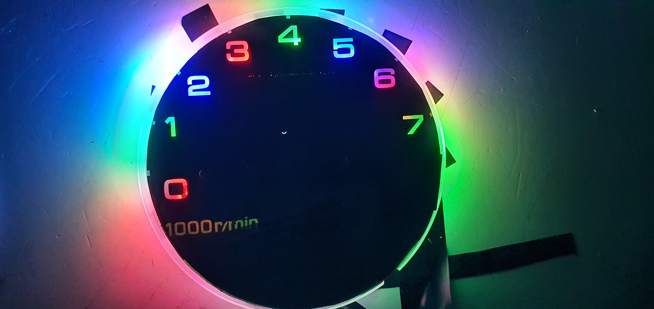
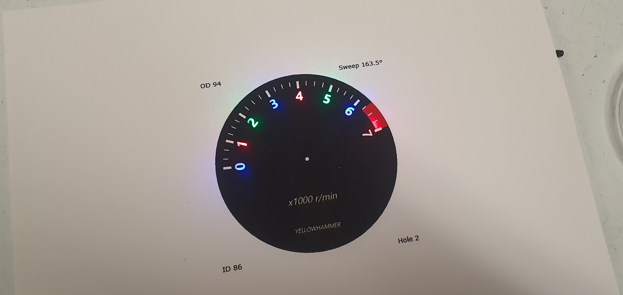
I then printed new faces with a revised, slightly larger, clearer font. I still might change it again in time. Easy and fun to do. Here's the light through the card..


Fitted into the casings..


Really happy with that.

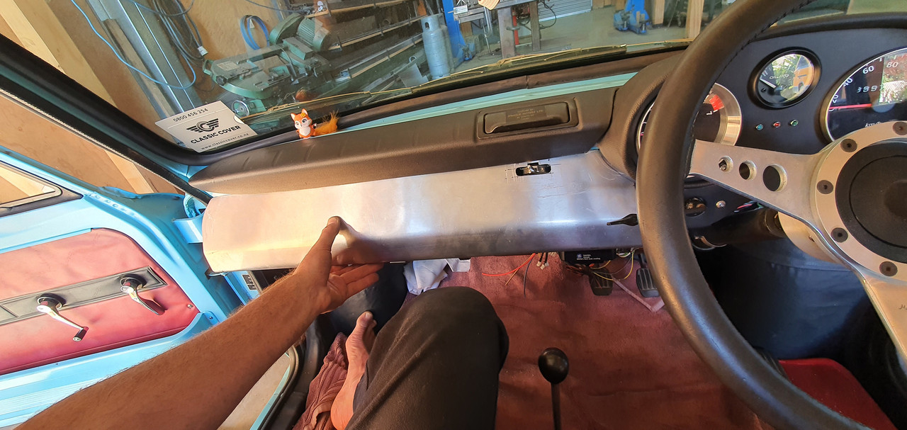
Now onto the dash build. I got the long folder out and some thin alloy sheet.


Folded up a basic shape..


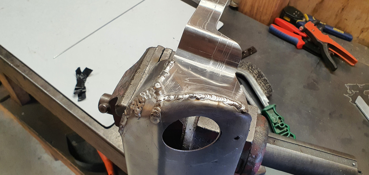
Cut, bent, hammered, welded it to a shape I fancied..


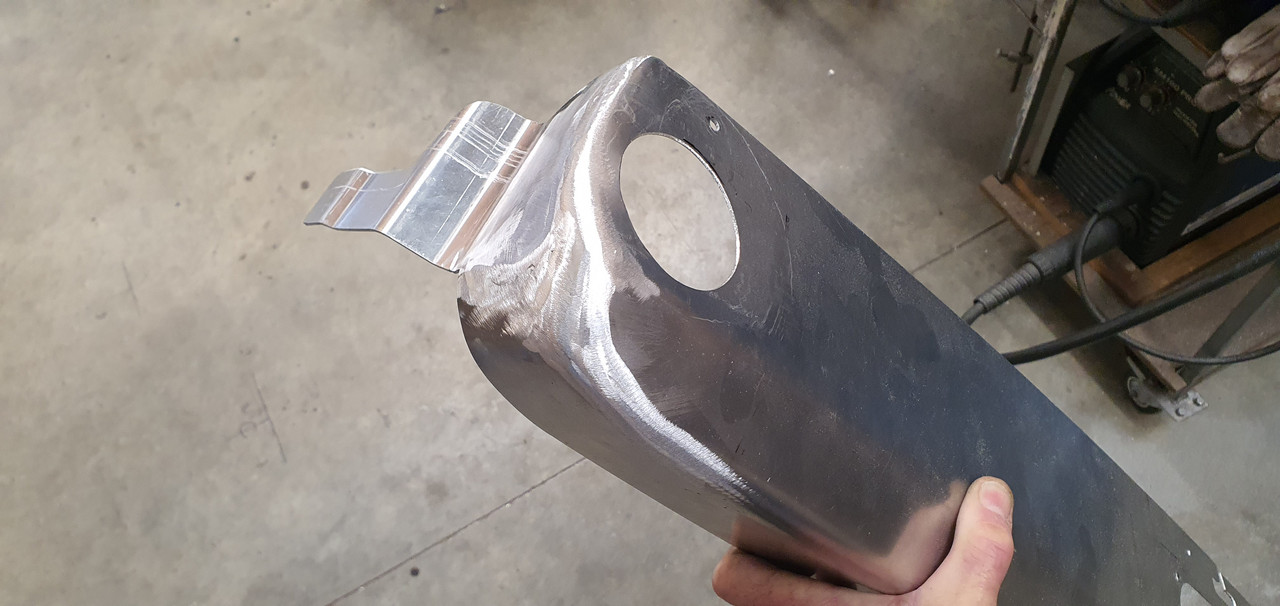
Flap disc and its now smooth..


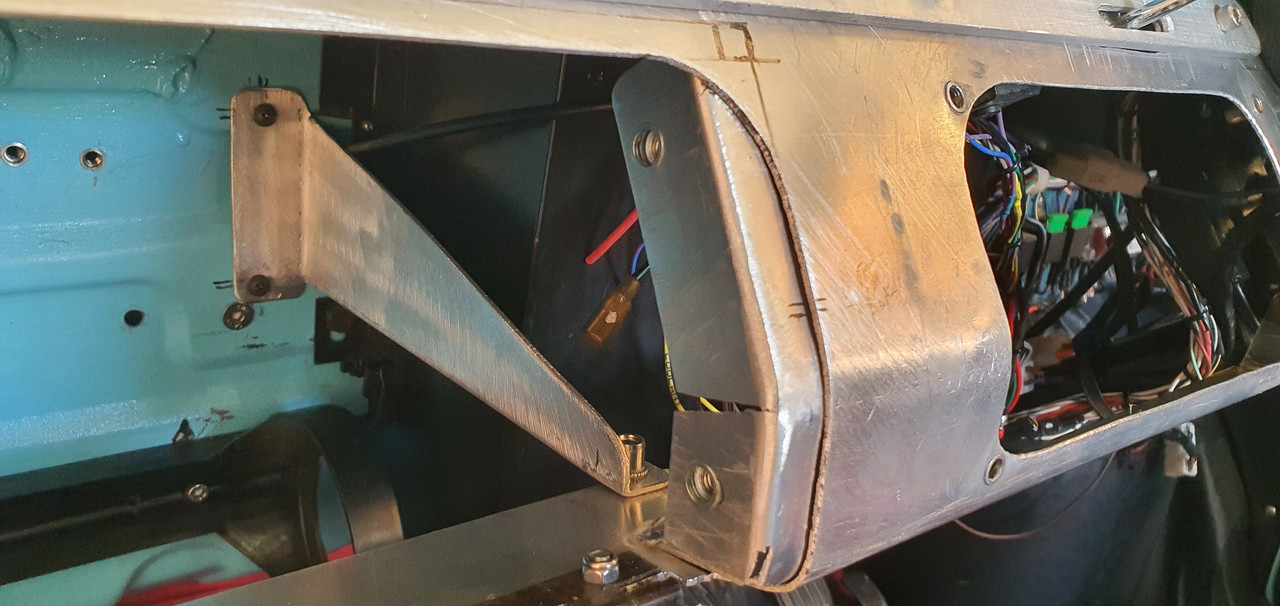
Screwed some alloy angle to the lip on the bottom of the dash panel..


Built in bracing and mounts for a bolt in glove box..

 
Discussion starter · #537 ·
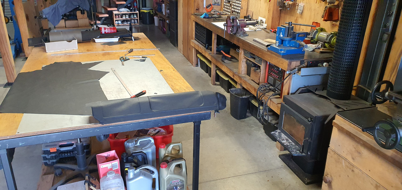
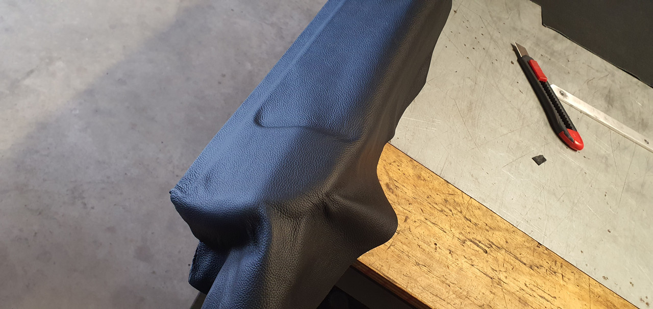
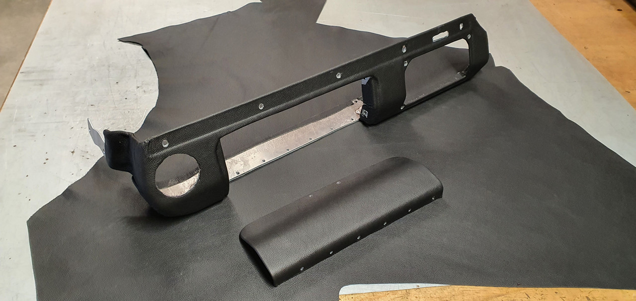
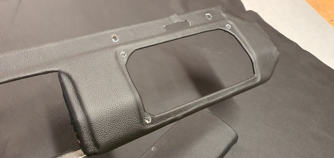
Once I was happy with the alloy structure I rolled out the leather. Lucky I'd bought plenty. I glued on one layer first, carefully cut to provide a stepped relief where needed. Then a second layer followed.


The hardest bit was the lower compound corner. Took some time and needed a cut.


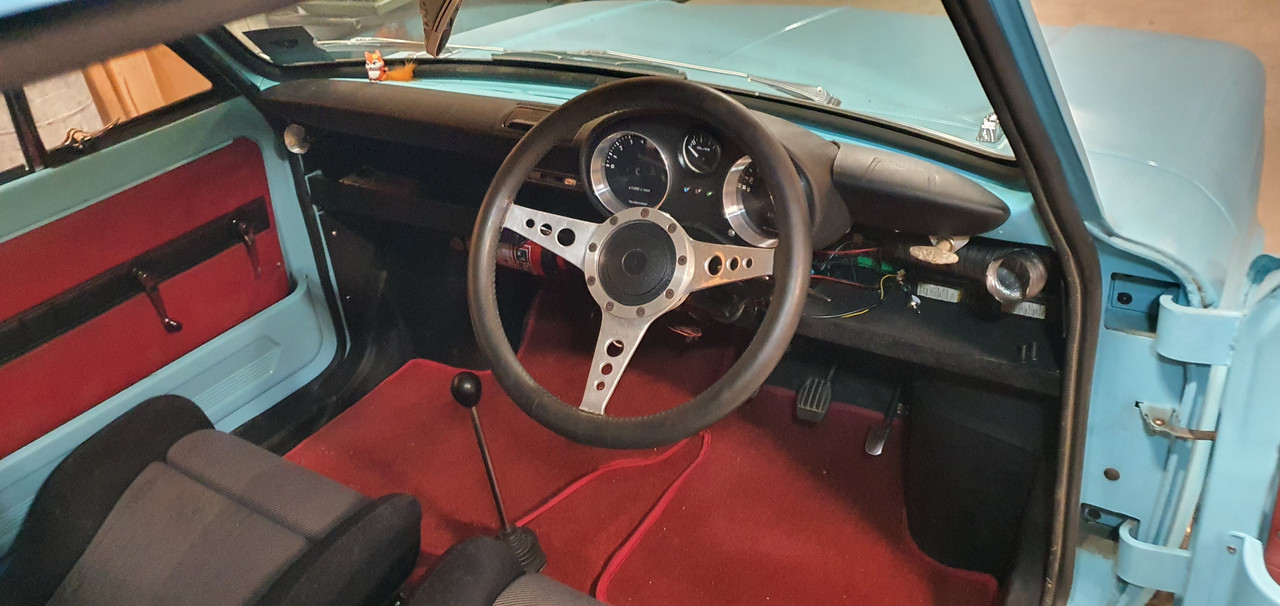
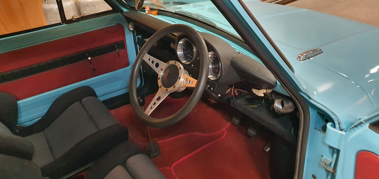
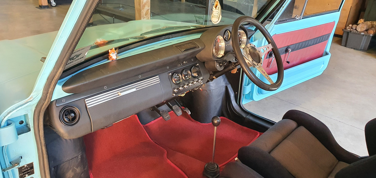
Very happy with the finished dash. Looks neat.


The reliefs are visible


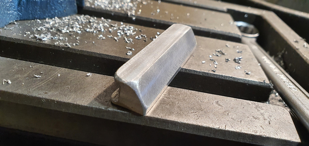
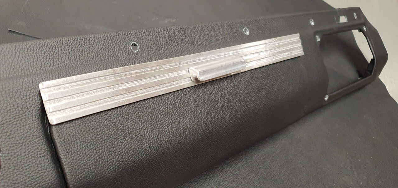
Next up was the glove box edge and handle. I machined up this little handle..


Fits like this..


There's a magnet hidden in another alloy strip on the back which clicks against another on a bracket off the dash.

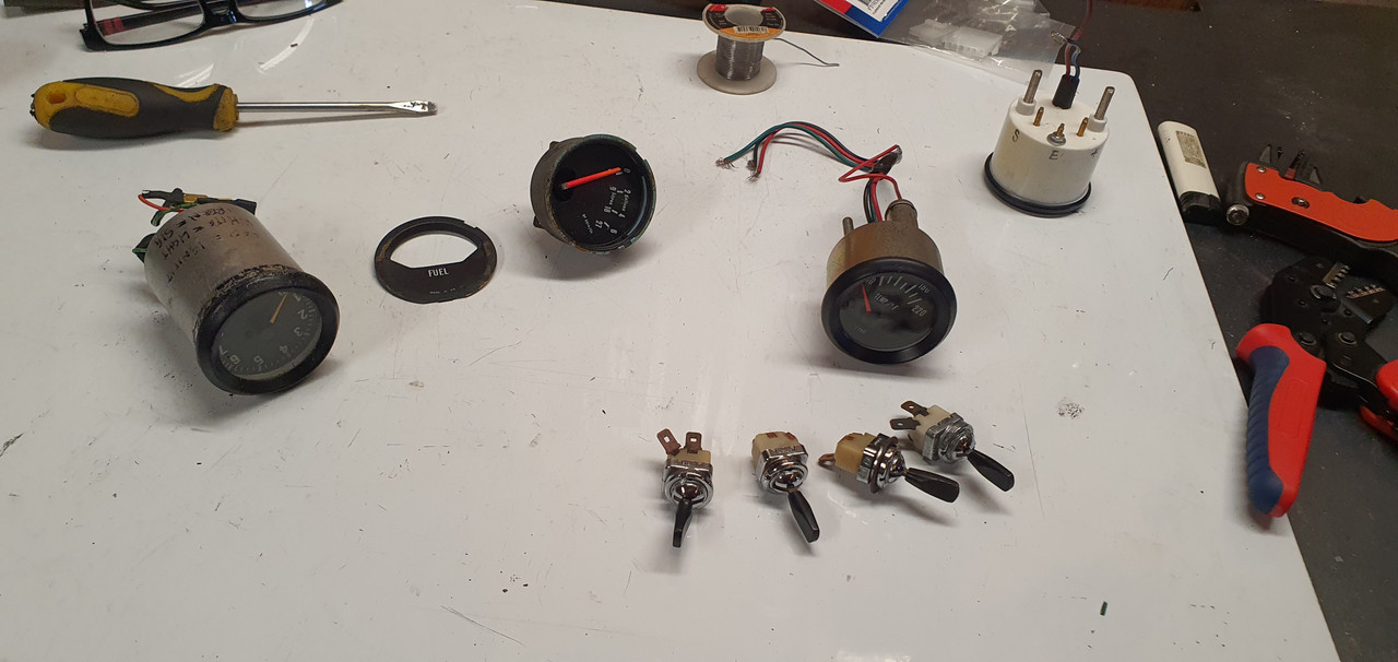
A fellow Imp nutter from Hamilton kindly sent a load of extra Imp switches and a temp gauge down to me and wouldn't even accept money for the postage! Thanks so much John!! :)


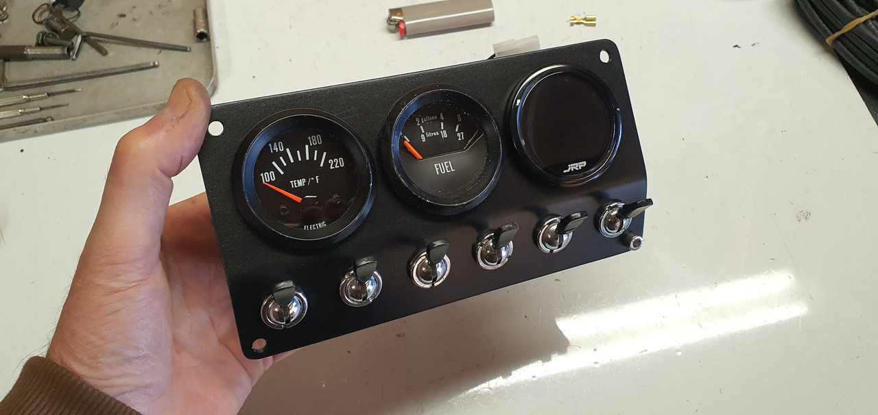
The gauge matches the spare imp fuel gauge but neither of them quite have the look I want so I have ordered another Trisco style fuel gauge to suit my Trisco water temp and oil pressure gauges. Hopefully I'll be able to get the new fuel gauge to work suitably with my Imp fuel level sender - which runs off a 5 volt regulator.

But for now I use what I have. All in place with my switches...


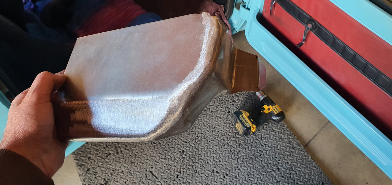
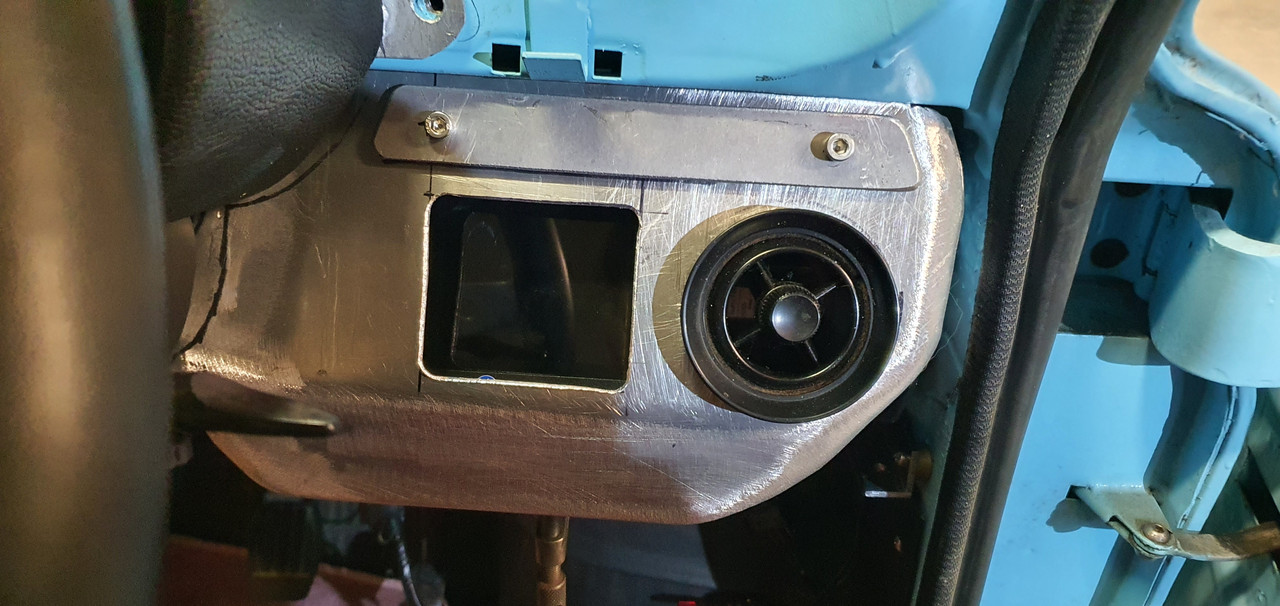
With the left hand side sorted I moved onto the drivers side. Same method. Manipulating some thin alloy, welding (tricky) and flap disc it smooth.


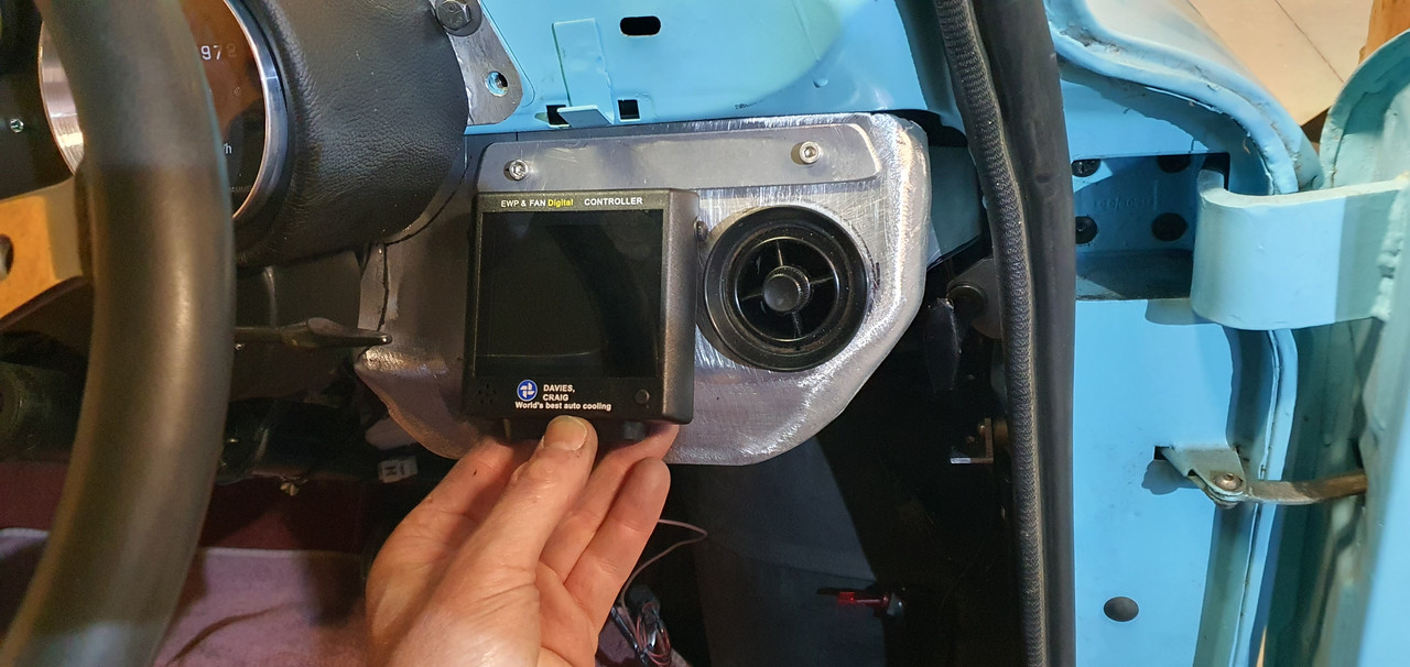
I have to allow for the ugly water pump controller. It has plenty of useful information so I don't want it hidden from view when driving. But it is ugly and not in keeping with the style I want.


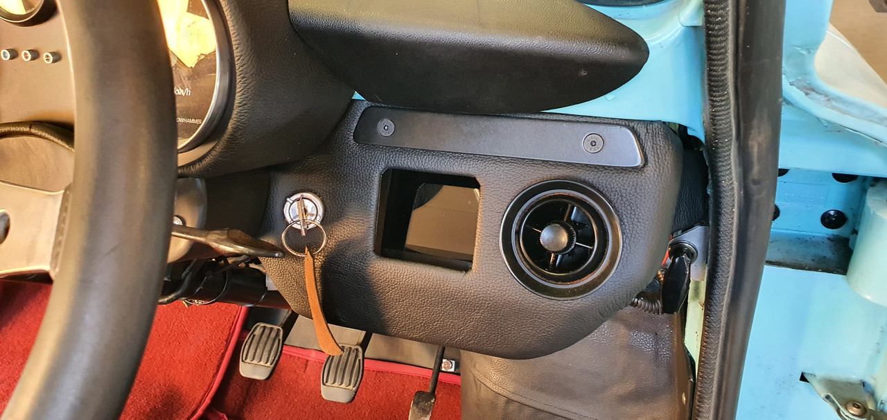
So I cut a hole, added a bolt in bracket to hold it at a suitable angle behind the hole. I will make some sort of slide down cover at a later date to hide the screen when not needed.


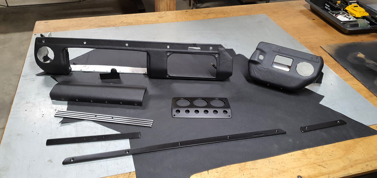
Added an angled face, drilled to suit the ignition key in a suitable usable position. Then covered it all in leather as per the other side. Here are all the bits together, alloy parts painted satin black.


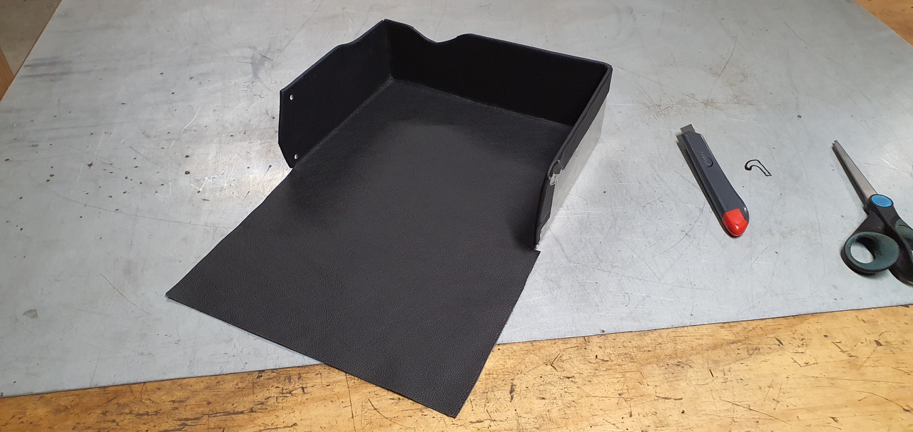
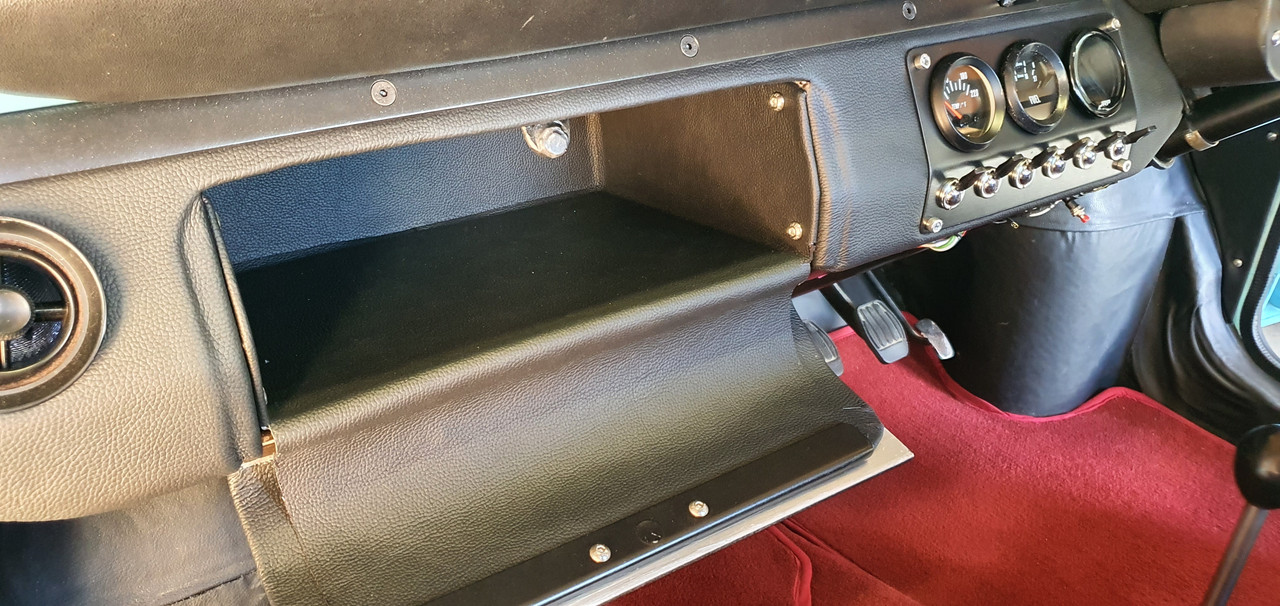
I carefully lined the glove box with leather too because why not..

 
Discussion starter · #538 ·
With it all fitted and bolted into place I was able to finish the wiring. I have added extra mini Molex plugs for all the gauges and switches, carefully designing the loom to allow easy simple removal of the units. There are two switches currently wired up but unused - one might be for extra lighting and the other for a suitable under seat bluetooth amp and active subwoofer. I'll be adding some tiny tweeters under the dash out of immediate view.
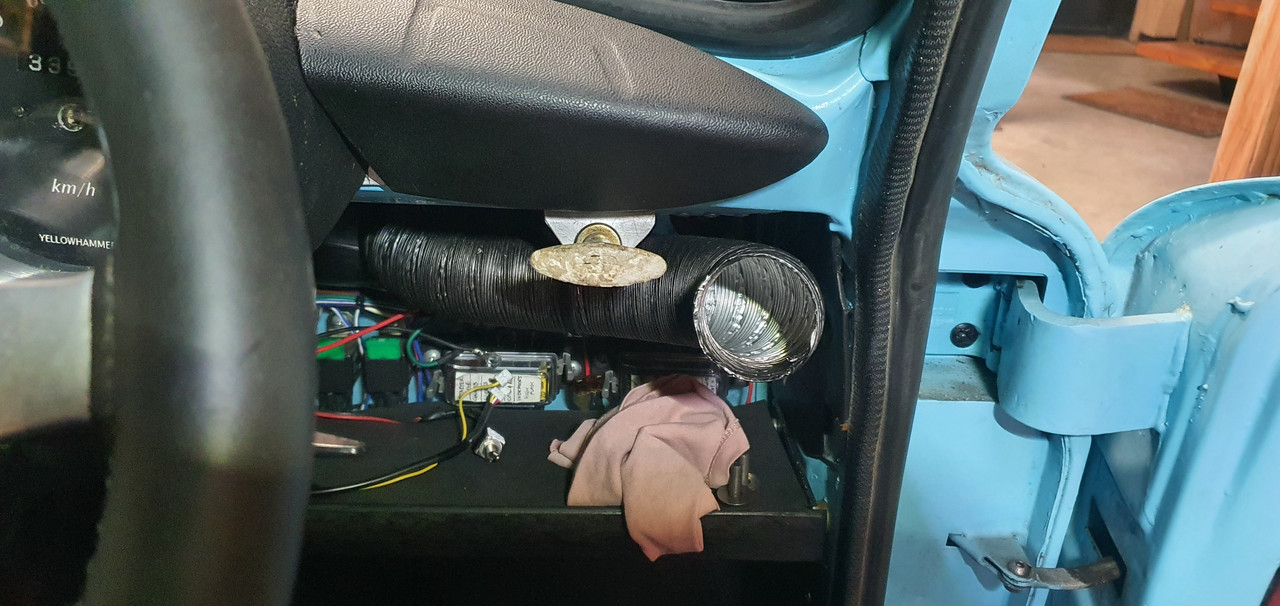
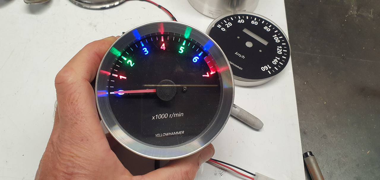
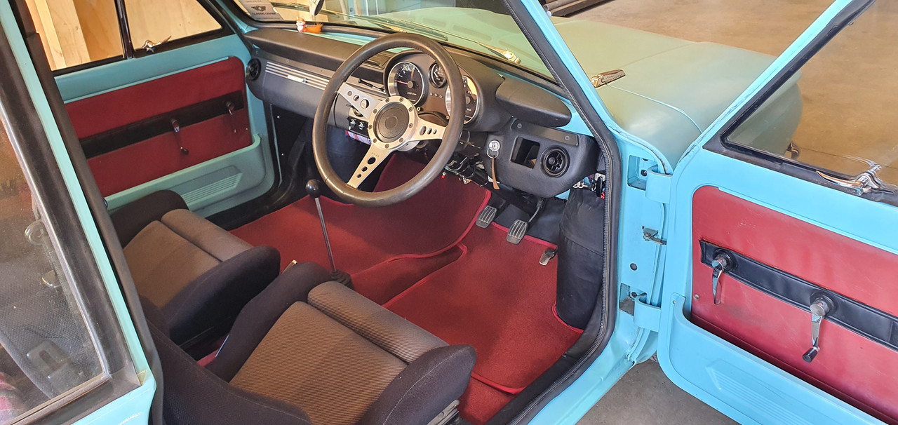
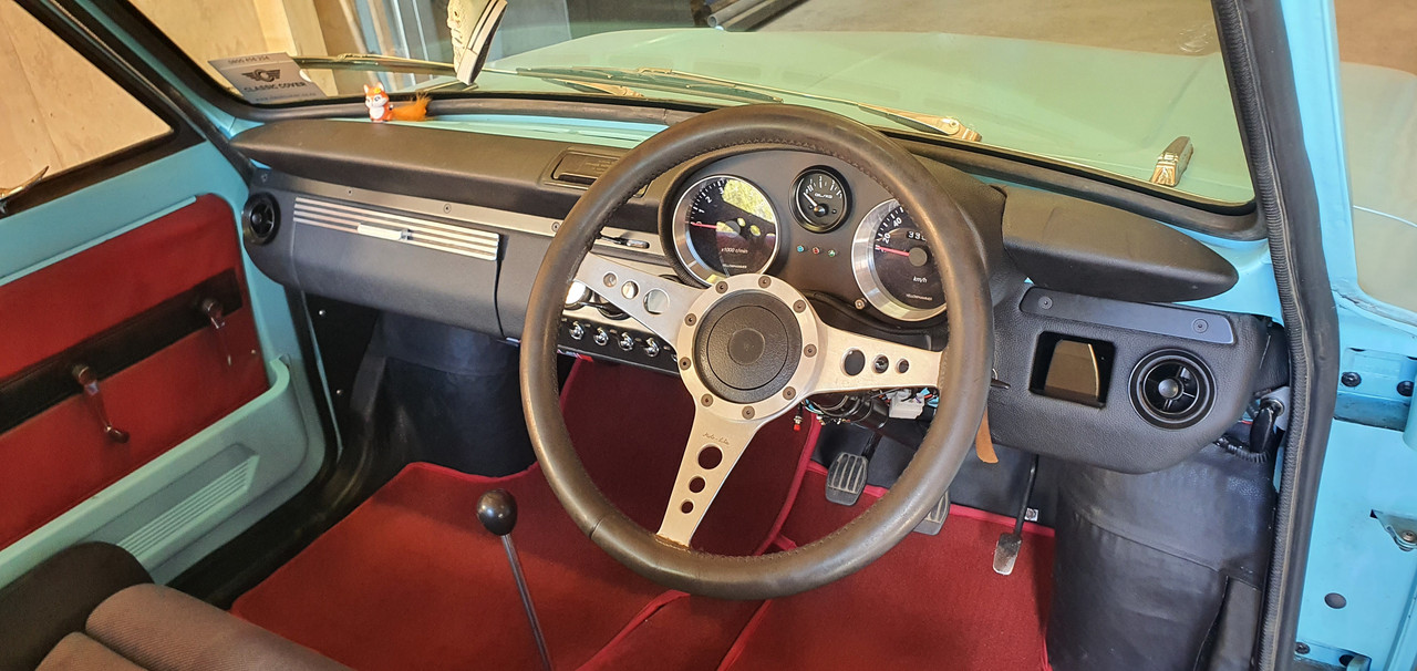
Wiring finished I started the engine. First start in a few months and it fired up beautifully. Rev counter works bang on and reads accurately. Switches all seem to switch as they should. Lights are neat. I took some photos with my phone. I might try for some better pics one evening with suitable light and the big camera.

Overall I'm really stoked with the resulting look and style. The leather work looks great. I have a couple of ideas for possible changes to the colour/style of the alloy trims plus a controller screen cover but will think about it for a bit first.


At a later date I will build some partitions along with a built in USB charger into the glovebox..


That little controller screen. I have some ideas for this but for now its usable as is.


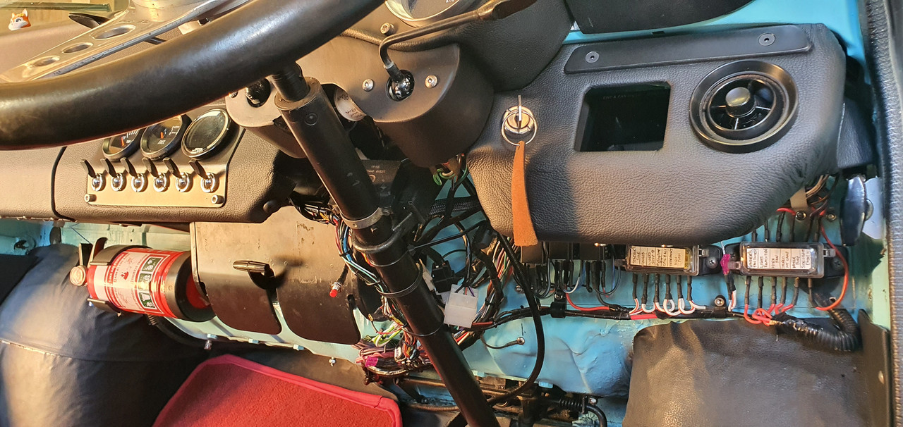
The current fuse and loom hidden from view below. I'm not going to tape it up yet until I have finished adding extras.


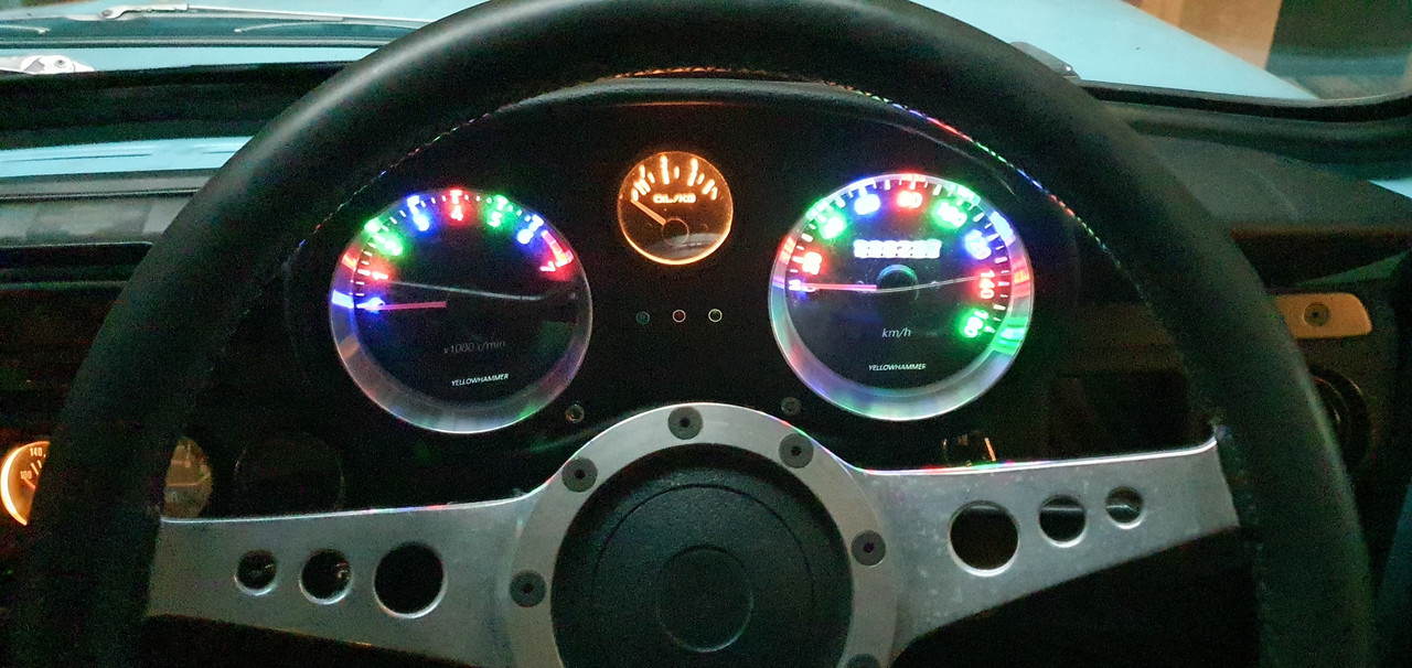
The main gauge lights. Bit tricky to get a clear shot on the phone. Needles do light up enough in use.


Phew. What a mission but great fun! Now its back to clearing silt and trees.
 
you sure are one talented artisan,
I marveled at the photo of your garage, and thinking how awful it would have been to come home to 12 inches of silt on the floor and around the metal on the racks next to the wall.

I don't envy you fixing that water problem, we had leak here, hard to find, but was an easy fix once located.
 
521 - 540 of 543 Posts