Steve Saunders Goldwing Forums banner

1965 Hillman imp with GL1500 engine. Road trip time.

110K views 545 replies 27 participants last post by  yoeddynz  
#1 · (Edited)
Hi all,

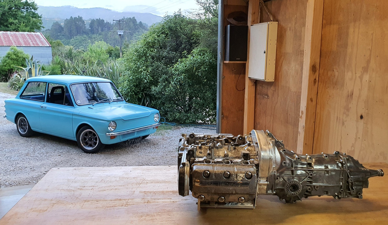
Down here in New Zealand I own this little 1965 Hillman Imp that I restored from Feb 2018. I am now looking into the possibilty of fitting a 1990 Honda Goldwing GL1500 engine to potentially build my very own baby 911 :)

This is my Imp...

321460


Here's the Datsun 1200 engine currently fitted...

321462


My plan is to remove all of the transmission and most of the drive gears from the casing. I have been looking over my Honda workshop manual and have pretty much nutted out the engineering that I'll need to do . However- before I commit I need to find out a couple of things. I thought I would ask on here and hopefully someone here will have a stripped down engine that they can get me some measurements from.

First thing I need to check is the thickness of the flange on the crank that the alternator drive gear bolts to. It takes 6 bolts. Also- what size are the bolts? They look like they could be 10mm? This is all important because I'll be machining a boss to bolt onto this flange and those six bolts will take the loading of a custom flywheel.

Here's a shot of the crank flange I need to know the thickness of...

321461


Another question. What is the measurement from the centre of the crank to the bottom of the engine. This is important to work out just how far the sump will hang from the back of my car once installed.

I'll be back soon with more questions I'm sure !

Cheers
alex
 
#91 ·
Back on the chain gang !

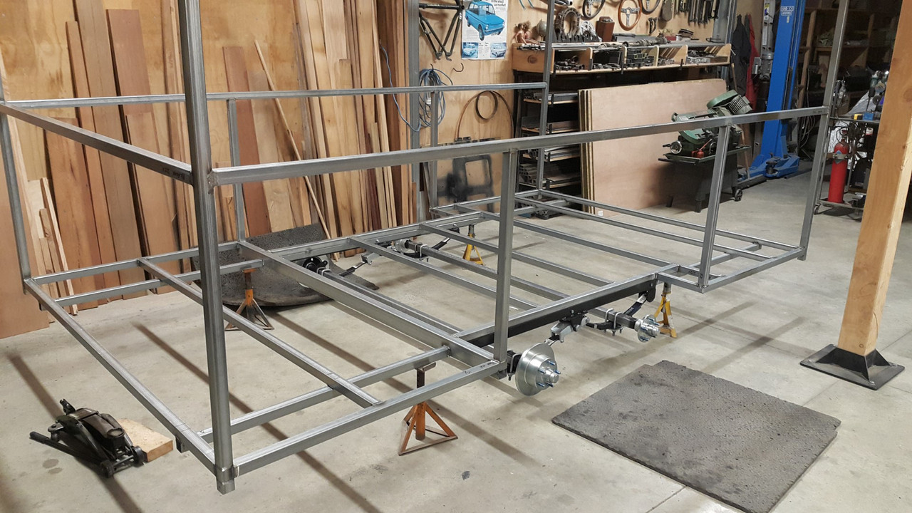
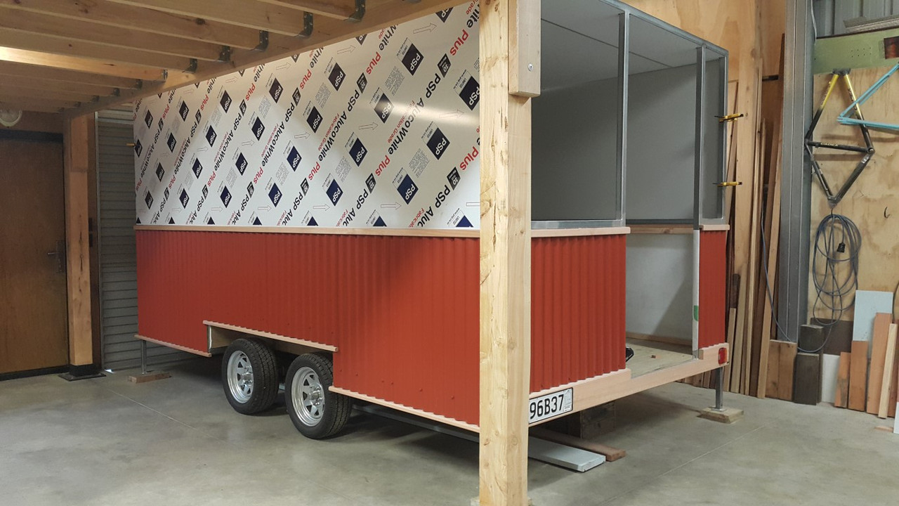
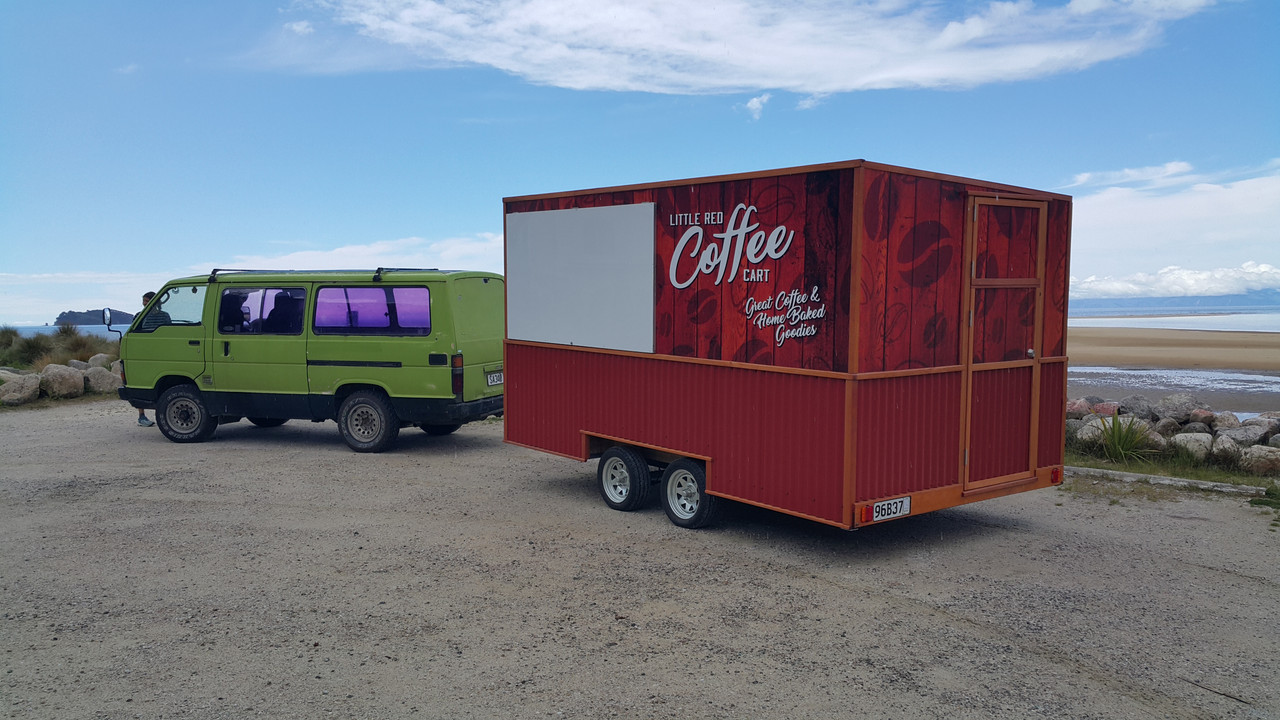
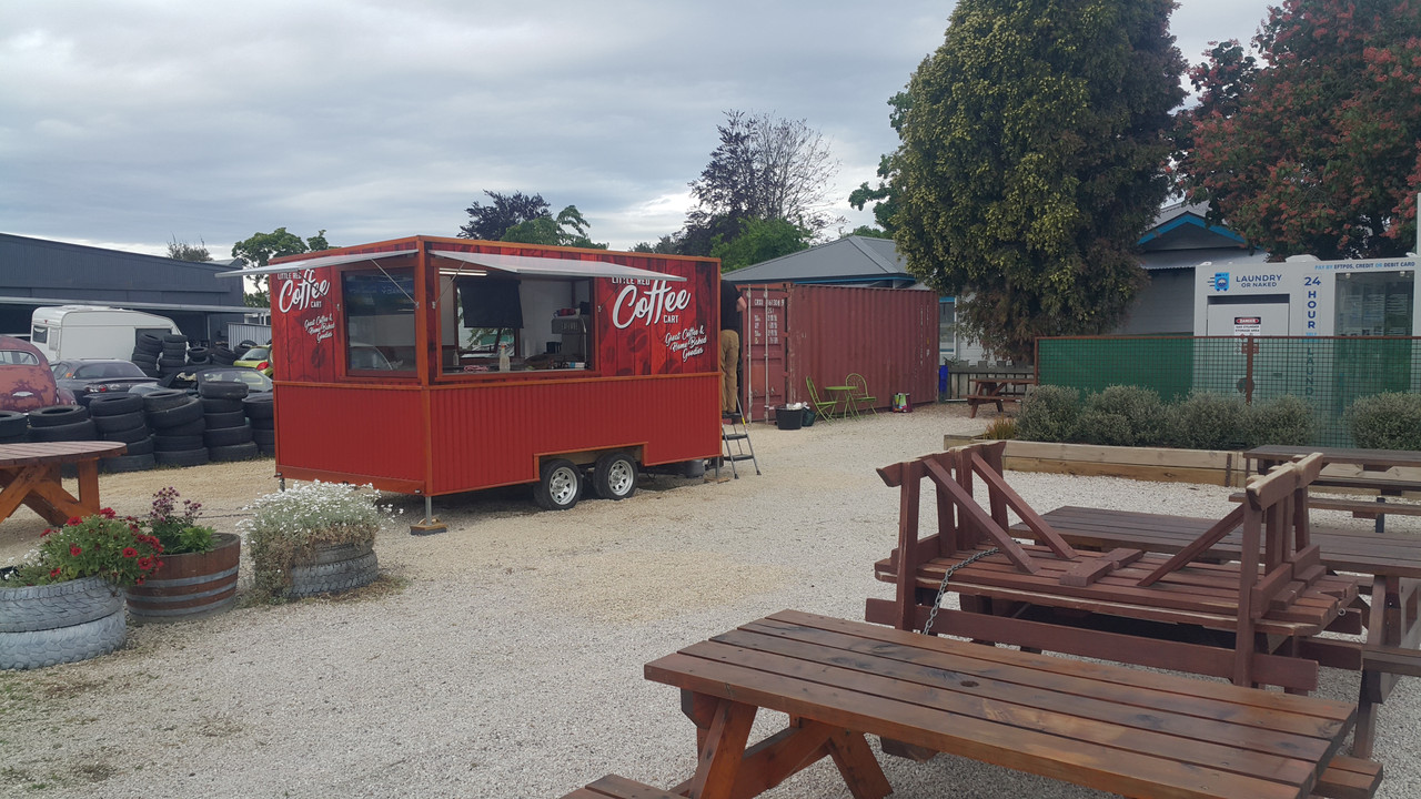
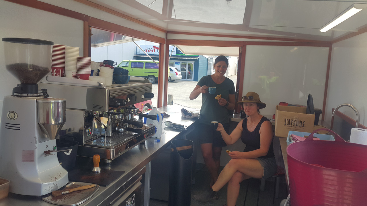
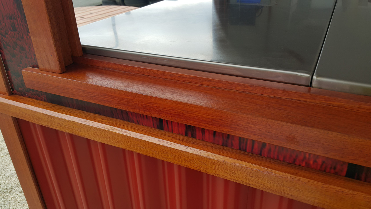
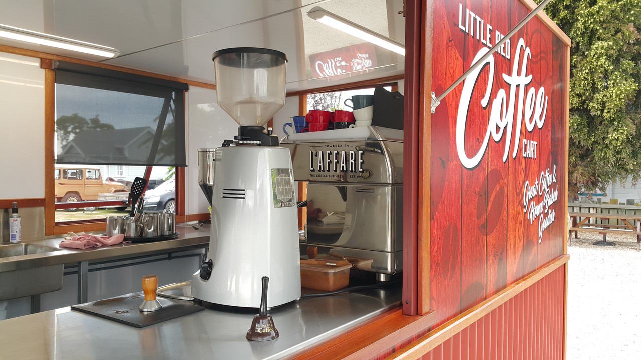
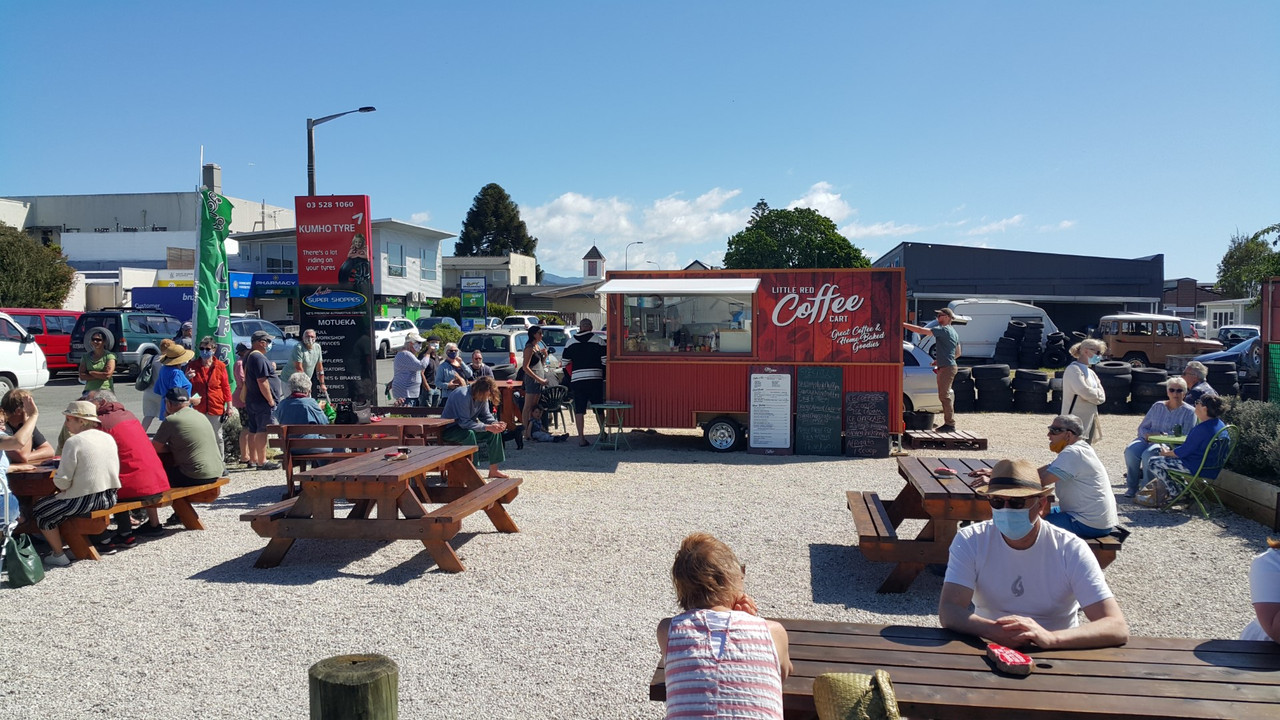
Yep. I'm back into this project. Its been a hectic busy last few months. Well for me, but others would probably laugh at my work levels. The last update was in September and both Hannah and I were pretty busy building a custom coffee cart for a customer. It was a fair old mission not helped by that pesky lockdown stalling a load of stuff ordered, including some double glazed window materials from Auckland. We put in some hard efforts to get the thing built and ready in time for the agreed date and managed it with a 2am finish on the last day before delivery. I was well chuffed with the cart we built and the customer is soooo happy with her new cafe ! All fully insulated, huge windows that roll away into the walls, loads of stainless benching and a lovely outside wood framing we made using Eucalyptus timber then oiled.

Here's some pics of the build...


Phew. Check that one off the whiteboard of jobs. Loads more work to chip through and we are now onto the steel framework for a local ladies housetruck. So I am going to do my best to just put down the tools, lock my bicycles away so I cant be tempted to just go riding and instead do more on this engine swap.

Most recent bits I have done are as follows.

I wanted to finish off the oil system. The internal stuff from the pick up to the pump and filter was sorted. Now I needed to get the oil from the filter to the engine. Luckily, well I kind of planned around it, there is a hole left where gear selector shaft went. This was ideal to pass a pipe back from the filter block outlet towards the front/belt end of the engine. But it needed to be bigger with some clearance. One big drill bit later...


next up was a plate to cover the front. What used to be here was a cast front cover, much deeper obviously because I have lopped off a huge chunk of engine casing. It housed the oil filter, now moved to the side. Instead of that I now needed a flat plate of thick alloy that will serve several things. The engine mounts, most likely typical compression bobbins, will be mounted off it. There has to be a way to get the oil from the pipe coming from the filter block to head back into the main oil feed hole higher in the block. Finally I need somewhere to put oil into the engine and also to check the oil level.

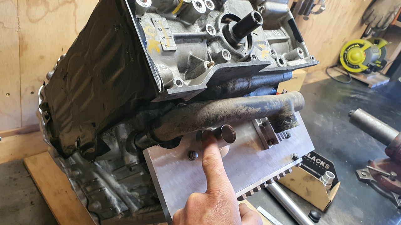
I started with a plate of alloy I roughly cut to size. Drilled it to suit the holes in the block that the old front cover mounted to. I then drilled a hole in it to suit the oil feed pipe. This was a hole perfectly located to make sure the pipe would line up with the filter transfer block nice and square. Because I'm using the O rings that Honda used throughout the original system. There is a small tolerance for being out of square with these but I might as well get it as close as I can.

 
#92 ·
I then needed to make a bolt on block that would take the oil from this pipe end and direct it through another hole in the plate which locates right over another O ring sealed port into the engines main oil way, just as the original front cover did.

I started with some more chunks of alloy and made a thousands of teeny tiny chunks of alloy with the tablesaw...


One of the blocks was then milled out to suit the pipe outlet and oilway inlet sizes. I also used a tiny little slot drill to add a groove to help keep the sealant in place..


Flipped it over and took more material away. Added some cooling grooves. But really.. come on. They were more just so it looked a bit nicer than just being a lump of alloy. Why not..


Clamped it down onto the front plate and drilled mounting holes...


There's a nice amount of room to still use the original honda cooling hose if I want but I may well do something else when I get to that bit- depends on my cross member design and engine mounts etc..


Next up was how to get oil in place! I needed a filler point. The original filler and dipstick are in the wrong spot and kind of chopped out. I could have made a dipstick to suit the now chopped down dipstick housing but that's at the rear/flywheel end of the engine. With the engine turned round 180 degrees that puts it under the parcel shelf and would mean reaching over what ever induction setup I use (cough*ITBS*cough) so that's not cricket.

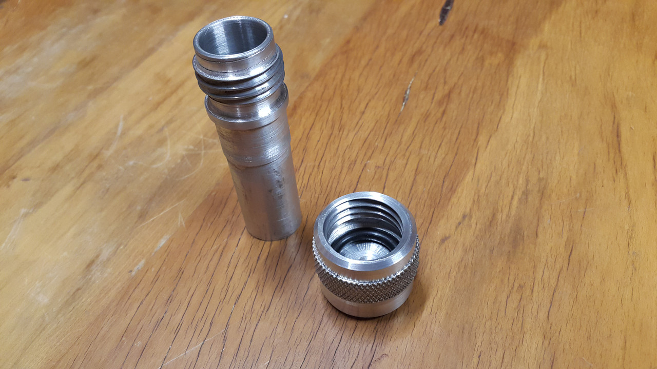
A filler tube, right at the front, but actually now the back, of the engine with a combined dipstick under the cap made more sense.

I rummaged through my collection of alloy..


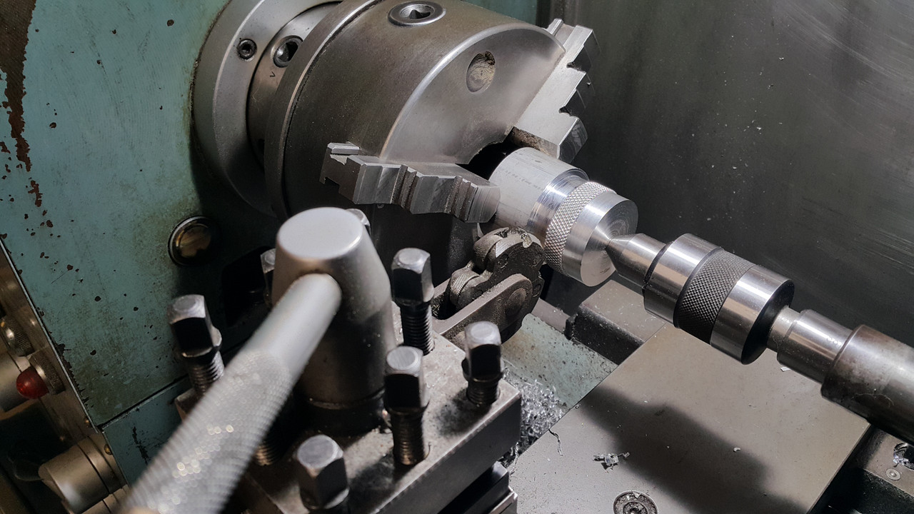
Playtime in the lathe...


and out popped this...


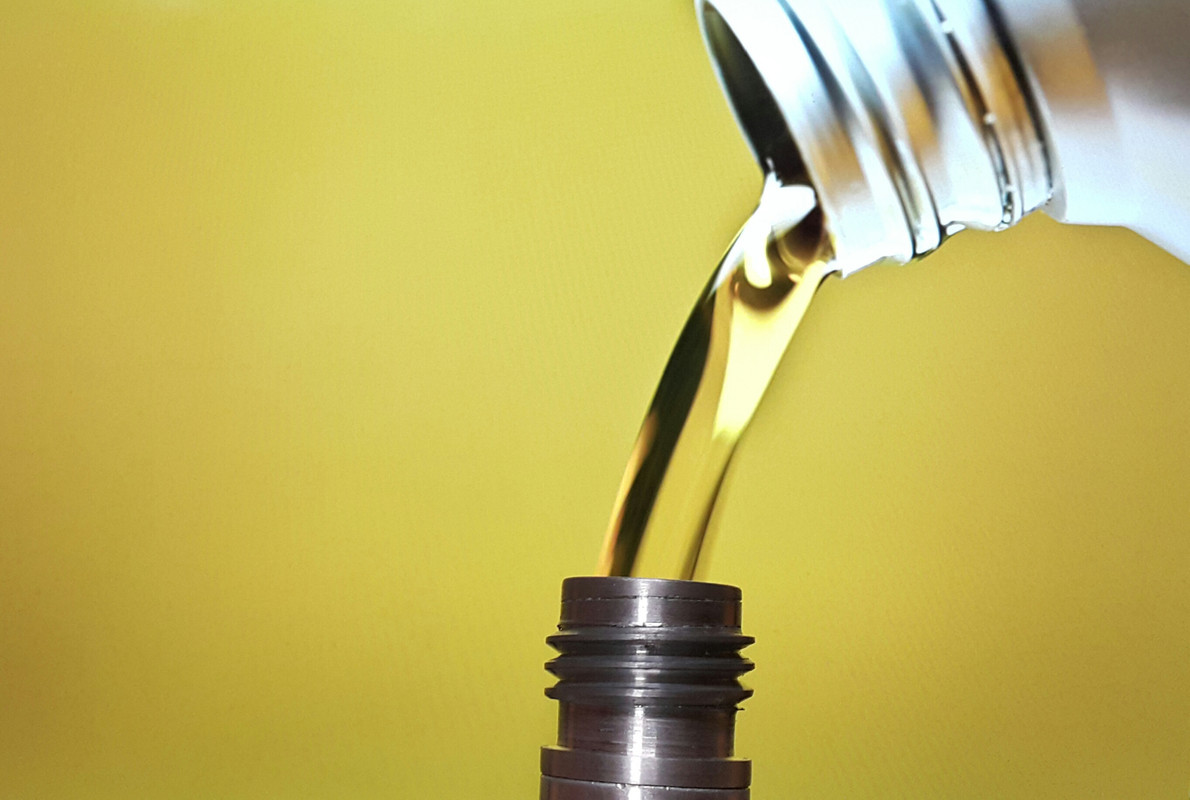
..into which oil will pour as such....


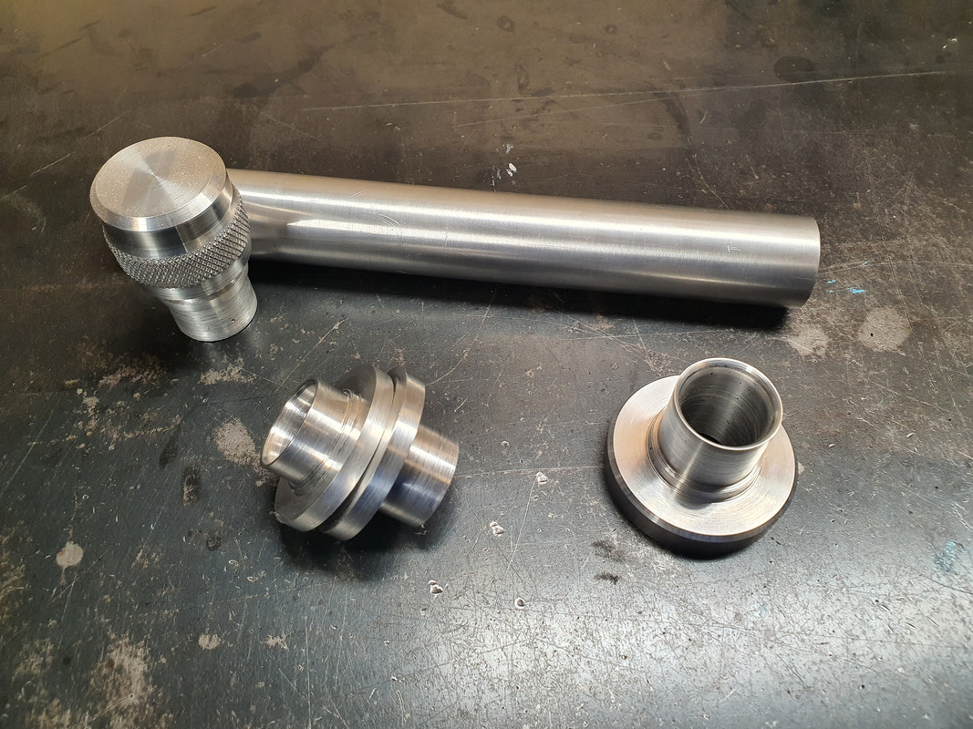
Now I needed some more bits to hold it in the right place so I made these flanges to suit more pipe.


Once I know what I'm doing with the cooling pipes etc I'll cut the pipe to suit and epoxy it into the flanges. I ideally need the main large flange to bolt over a hole below the oil level height - which I have roughly worked out allowing for about 4.5 litres thereabouts. This pipe and cap will be right there, on view, easy to get to at the engine bay opening. The two smaller flanges are so I can remove the upright pipe to allow for the cambelt covers to be removed, or so its not there liable for getting damaged when removing and moving the engine about.

I did think about being super silly and adding a sight glass to the pipe. Or use some thin glass or plastic tube. I then even thought about being really silly and adding an led light into the pipe to light up the oil.

But oil does not stay honey clean does it. So a neat little dipstick under the cap will do.

Lastly I needed to bolt the sump cover in place. I had to think carefully about bolt placement for sealing purposes and get the bolts square. This sump plate is going to have to be sealed well because there is no usual high sided sump like most cars. Hence I built it rigid to help against flex. Good quality sealant will be the order of the day*

To get the bolt holes square I had to do this...


Impy sat outside looking in at his new heart being crafted (said like some car obsessed bloke who anthropomorphises his cars)...


Well then. That's it. Crikey. Another wall of text. I hope you enjoyed my ramblings. I promise I'll put more effort into working on this (but it is summer after all..)


*It will leak. Its a British car. Its destined to leak.
 
#95 ·
sure have missed you posting regular, glad to see you back today.
I've been having internet issues in the way of:
some websites won't let me see them, this forum does,
BUT, is it just me, or did the pictures now show up in the last two posts.?
 
#101 ·
This is the most interesting thread I have seen on any forum!

Thanks for posting.

Rayjoe
Hey thanks for the appreciation Rayjoe and also the others here who are enjoying my bit of workshop tinkering. It does help knowing that others are following my progress with interest.


Well,
brought up this page of the thread, hit F5 and went off to tool around the house, made breakfast, and then came back to a lot of very good pictures :)

I think my Download speeds of late, are at the immensely speed 0.500 kHz
T-Mobile seems to be experiencing a lot of Holiday Rush ills... :(
I have the same slow internet issues here. We live in a small valley about 3km from the nearest village - most of that village now has fibre optic broadband with better speeds but they'll never run that out to the few farm houses surrounding it. Its worse right now because of all the holiday makers making there way to Marahau for our beaches and hogging the internet :rolleyes:

Some friends have moved over to starlink and said its fantastic. But there's no way I can afford that.
 
#102 ·
T-Mobile is working on their towers,
the one that we use here is 7.5 miles NNE of us, and it used to only provide me with 3.5 to 5 Mbps down, and uploades in the sub 1Mbps range.

over the Christmas weekend, it went all to hell in a hand basket, but it must have been due to a massive reconfiguration, because today, we at in the 54 Mbps range


Image
 
#103 ·
I think there were widespread issues with DNS yesterday that caused general slowness and many websites to be intermittent or unavailable.
 
#104 ·
I received a tech newsletter sometime last week, that mentioned that Amazon's AWS web servers went down, and that effected a huge amount of web traffic.

Our forum here is on CloudFlare and they were not effected, as anyone who uses "CloudFlare DNS" did not experience the issues.

for me, the web consisted of
this forum​
Yahoo email ( but it was terribly slow )​
Facebook​
LinuxMint forum​
Google - Email, news, maps​

things that I could not reach were
The Weather Channel​
Weather Underground​
Weather Bug​
Imgur.com an Image hosting server​
and a lost of stuff that was linked out of my emails, that i normally read​


After I received the "fix from T-Mobile" yesterday, all of the Internet World came back to me.
I can only assume that when the DNS issues occurred that the links from TM to the DNS servers were changed...

In any event, DNS is still working for me this morning.
 
#105 ·
Even on my Fiber internet the long post with all the pictures was missing half the pictures until I hit the refresh button. So something on the internet was clearly sub-par and messing with the photons.
Thanks, yoeddynz, for the update! Impressive work!
 
#106 ·
Fantastic build. Very jealous of your skill set. Look forward to the next installment.
 
  • Like
Reactions: yoeddynz
#107 ·
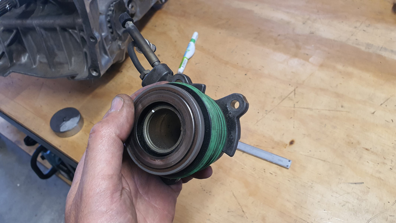
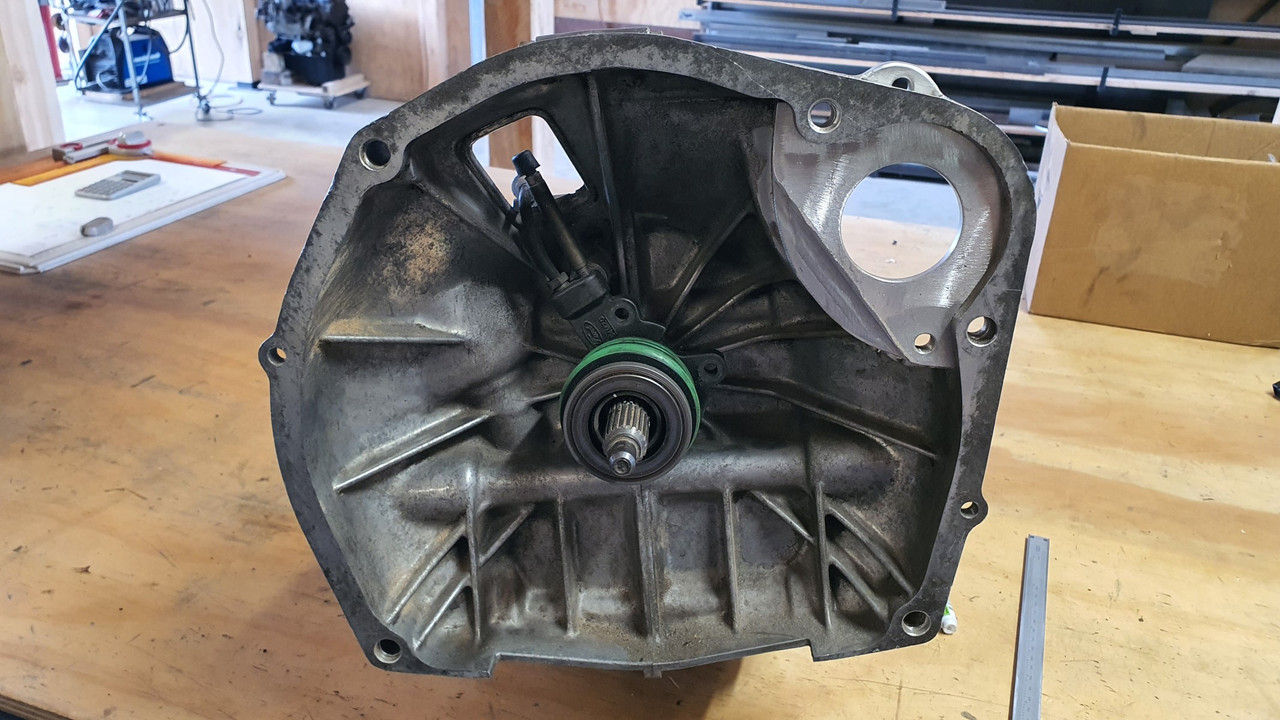
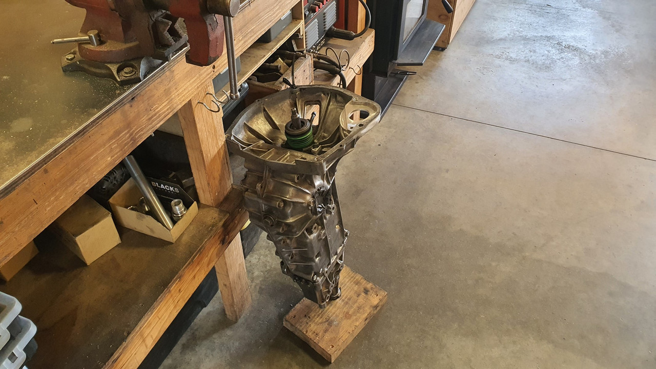
Next step in the puzzle was to sort out a clutch release system. I had a couple of options that could work. I could use the stock Subaru fork but it was not ideal for two reasons ;

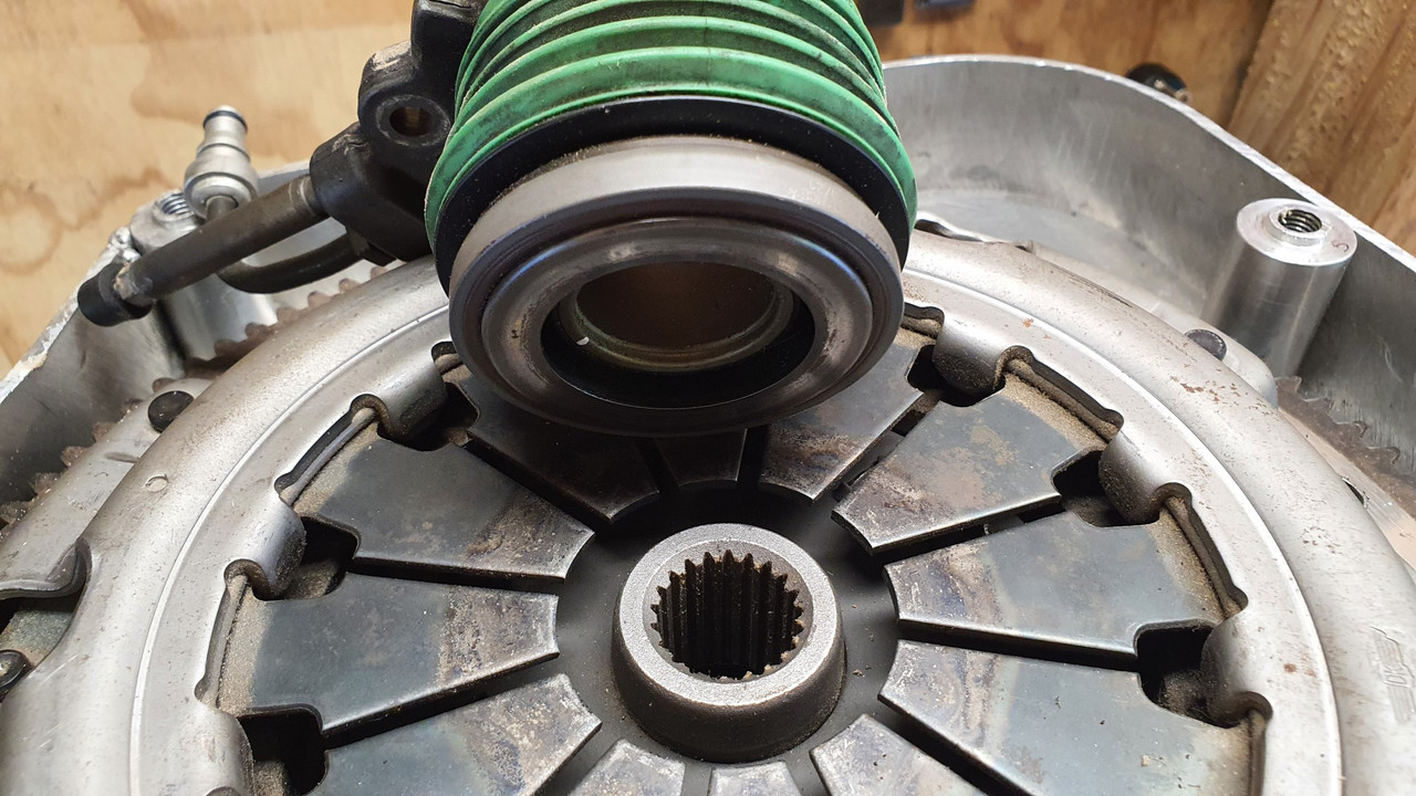
1: It would need a the release bearing carrier adapting to take a larger diameter bearing that would suit the Honda pressure plate fingers.

2: Its pivot location, being a centre mounted fulcrum point, would require a slave cylinder that pushed it towards the front of the car. This is because originally the Leone the transmission came from uses a clutch cable. I'd being using a hydraulic slave and it would have to be mounted up high, over the engine. Probably clash with the underside of the parcel shelf and would definitely look ugly there.

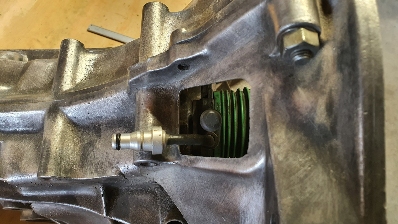
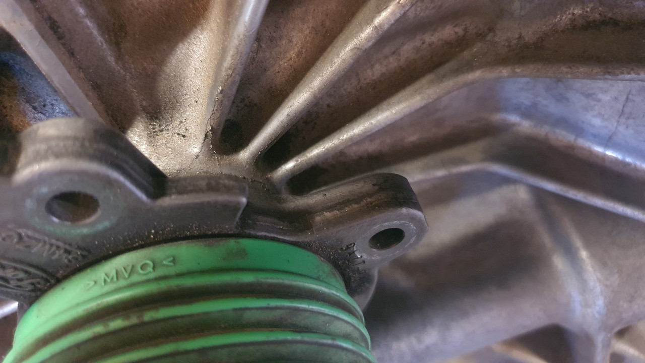
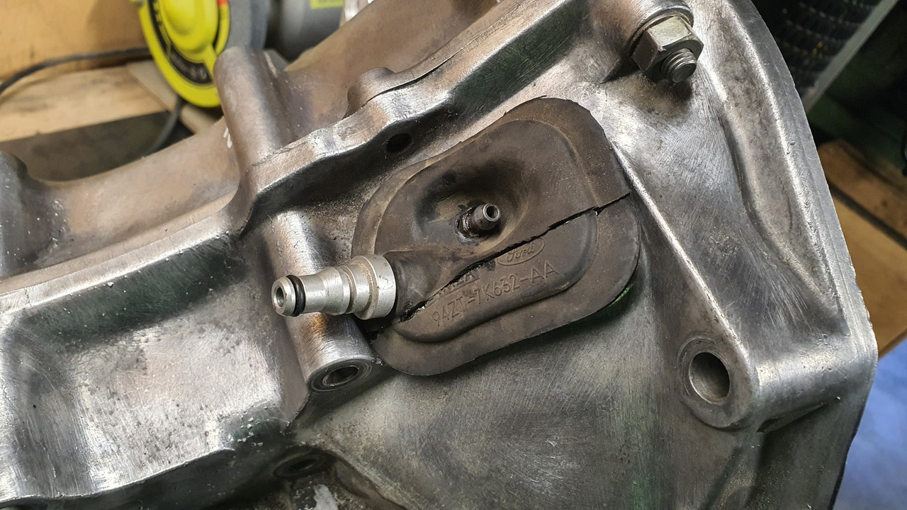
Option two was to use the Ford Mundano concentric slave cylinder I have had stashed away for ages, acquired with the Duratec engine I was going to fit into the Viva wagon many moons ago.


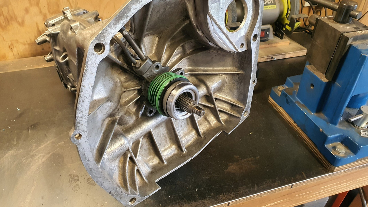
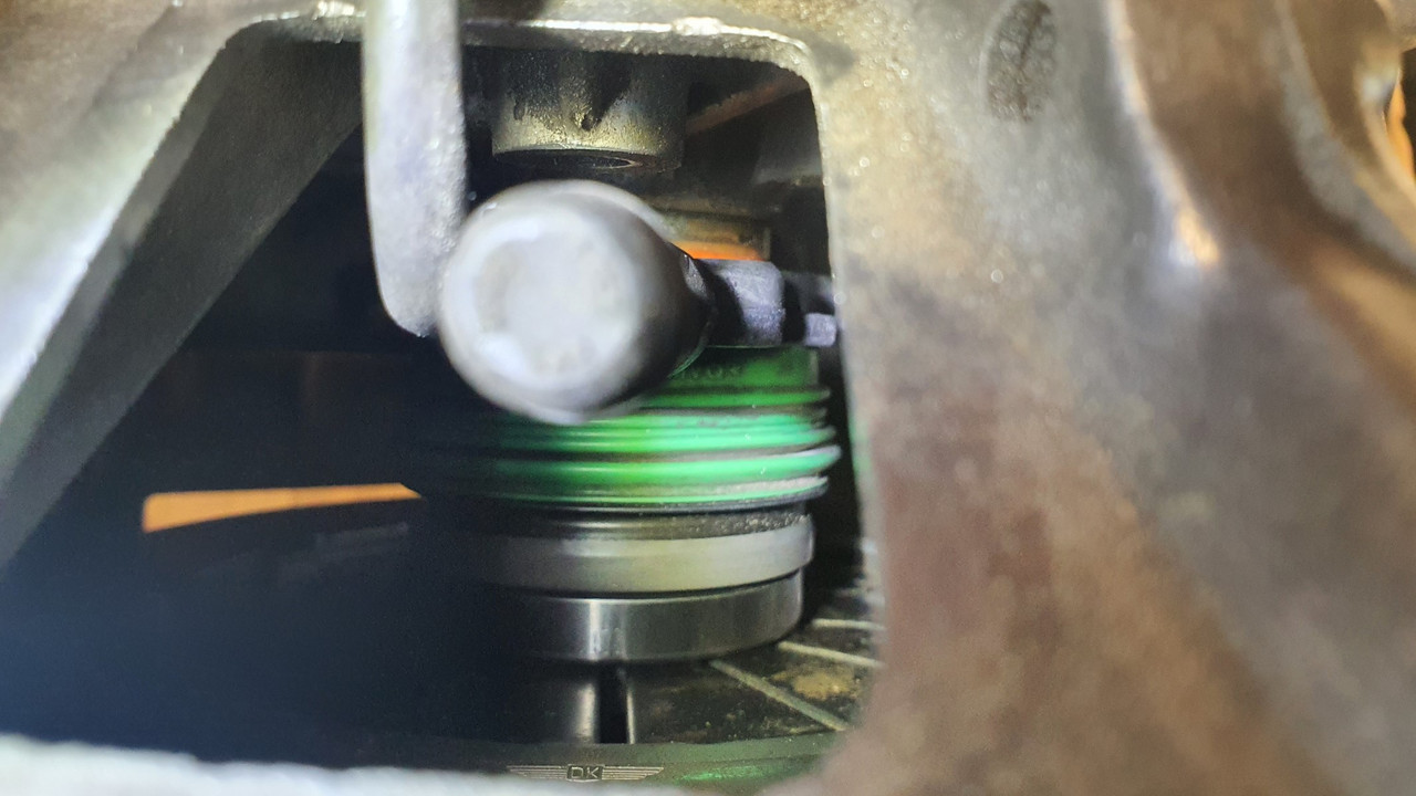
This certainly seemed the most sensible option because it fitted into the location almost perfectly...


The pipes even pop out through the Subaru release fork hole like it was made for it...


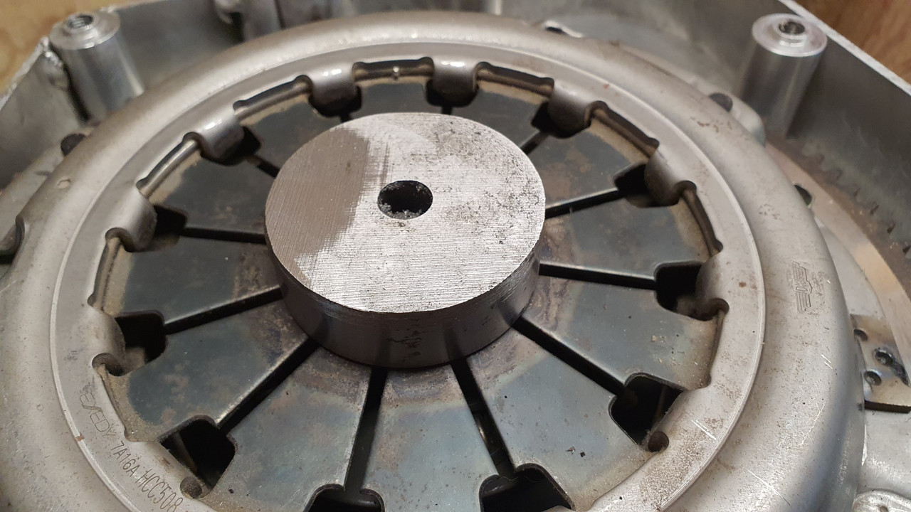
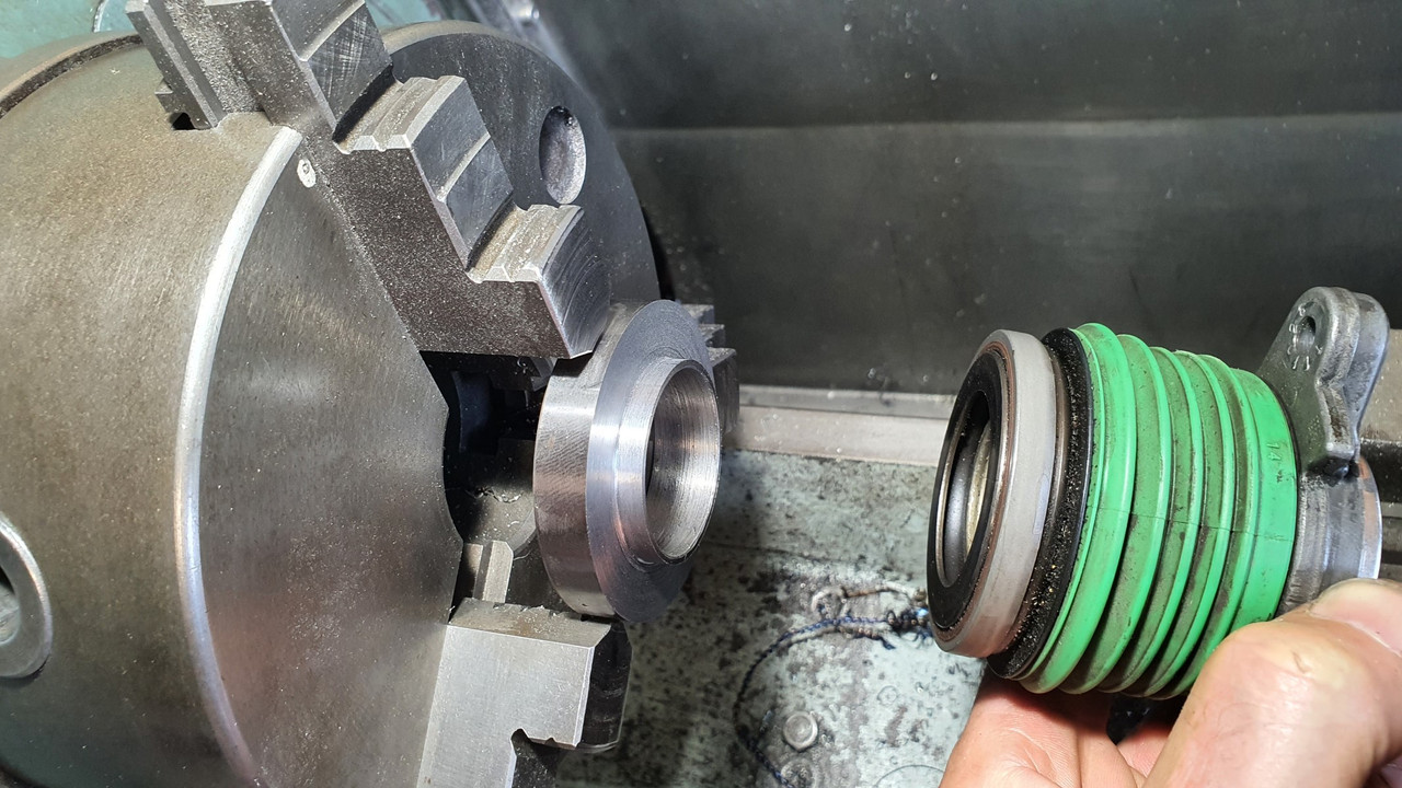
But it was still going to require a little work. First off is that it has a flat bearing face, made to suit curved diaphragm spring ends. It was also too small in diameter to suit the fingers.


So a lump of steel was plucked from the store...


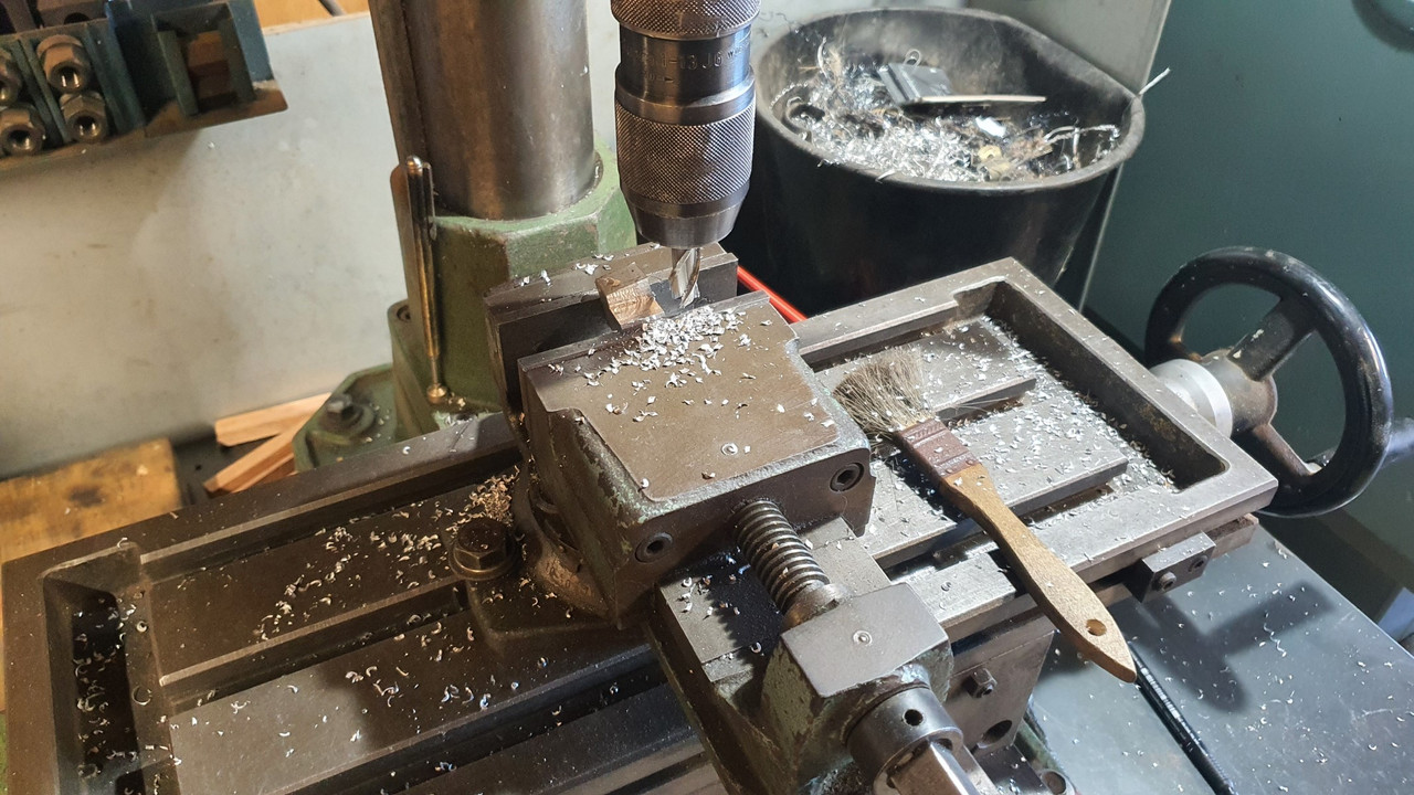
There was just enough room between the bearing face and the 'slidey hub' bit that the bearing hydraulics slide in and out on for me to machine a locating stub onto the bit of steel...


With that being a perfect fitting locating point the other side was machined with a radialised face to suit the flat fingers. The end result looks like this..


This will be stuck in place onto the release bearing face with something like loctite 601. It cant go anywhere anyway.

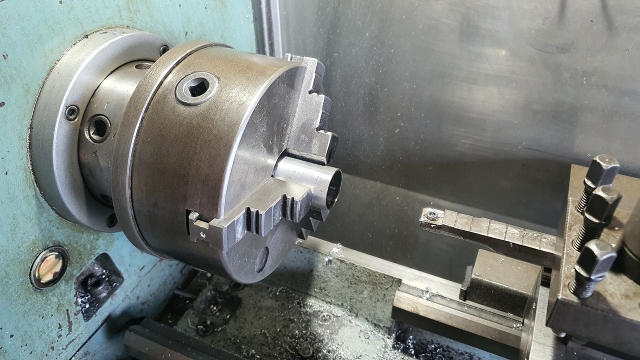
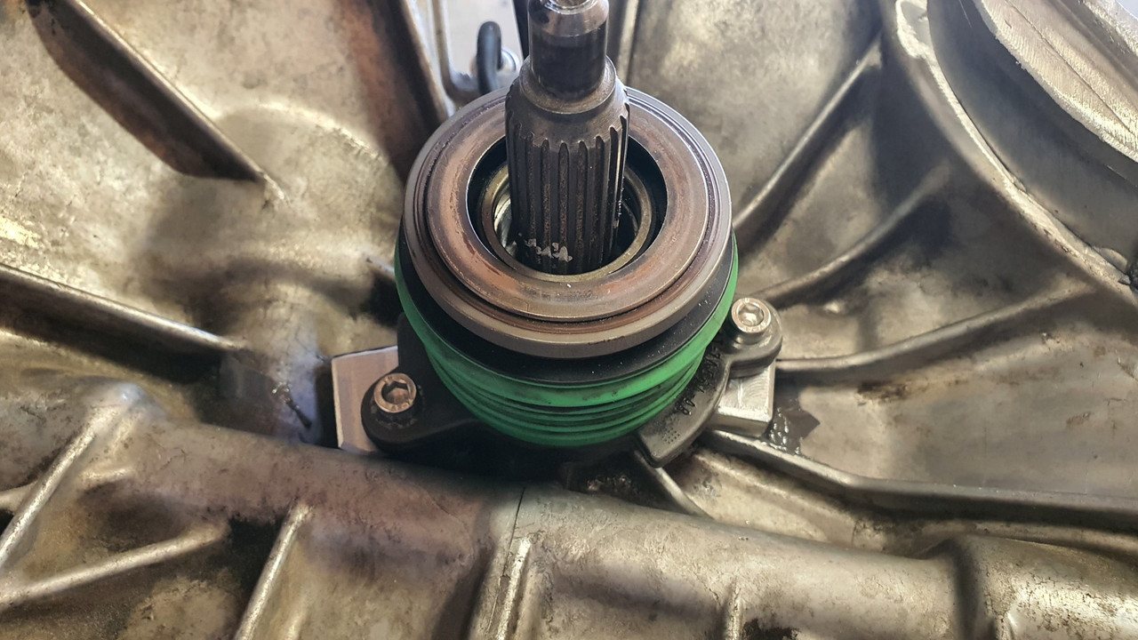
Next issue was fixing this whole unit in place and making sure its dead square to the input shaft centre line. Luckily the units bore was larger that the stub/shaft?* that the Subaru release bearing carrier slides on by about 2mm. It also so happened that when pushed on as far as it would go it allowed for just the right amount of movement of the release bearing, plus a bit to spare.

So I machined a thin sleeve with a lip at one end to suit..


This I made a nice snug fit onto the stub/shaft thing and the Mundano assembly slides in place snug, thus making sure it all remains square.

I assembled the lot together and checked it all with the transmission bolted in place. Looks good..


The initial throw of the release bearing will be adjusted at the pedal, which will now require me to either use the Mundano master cylinder (plastic..yuck) or machine/ sleeve my Imp one (actually the same as a landrover/most trailer brakes out there..) to suit. I'll look at that when I get to it.

Next step is to bolt the assembly in place. The Leone box has splines cast in around the stub base...


..but luckily enough room between them to glue some blocks in place so I machined some alloy down to suit..


Because I knew the assembly was perfectly straight and in line I just needed to give enough clearance on the blocks to allow for some epoxy. I drilled and tapped the blocks to suit, mixed up some of my favourite JB weld and filled the chosen cavities then slide it back in place. Then let it set overnight..


The next day I tried the original Mundano rubber boot for the pipe exit. It almost fitted. I sliced 5mm out of its width and it was sorted. Not perfect looking but it works and cant be seen once the engine is in place anyway...


Phew. Done. At this point I really did have a feeling like I had made it past the trickiest bits of the engine work required. But for some possible baffles around the oil pump pick up and maybe an anti surge plate (not that the Goldwing engine has any as stock) I think all the required mods to the engine are done. I felt like having a cold beer.
So I did. Then pondered the next jobs to do.

Which was to look at where I would run my cooling pipes and finalise the position of the oil filler tube..


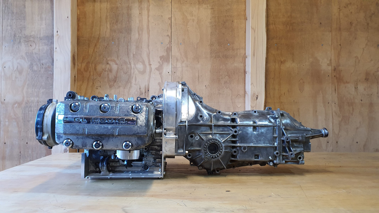
In order to properly work through some routing ideas I had to plonk the heads back on. With them in place I might as well have some fun, bolt the transmission on and stand back with my beer and gaze at it all.

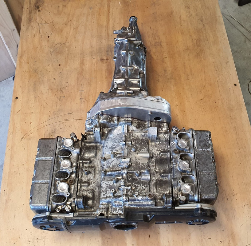
I took some pics. I'm pretty bloody happy with it how it looks and I really did get a mojo boost looking at it sitting there as a complete unit waiting to go in...


Its so neat and compact for a flat six..


Man I'm looking forward to having this setup in the back of my Imp! What's nice to think about is that while there's still a big load of work to do these next jobs will be super fun. I'm especially looking forward to making the ITB arrangement to suit and doing my best to create a really clean looking engine bay.

 
#111 ·
Thanks fellas.

I'm going to machine a pully to drive off the shaft end. Lucky there's a keyway and a substantial bolt there. Then I'll mount the alternator directly above. Planning on making some sort of neat arrangement to raise the alt straight up to tension the belt because I really want to make this engine look as symmetrical as I can :cool:
 
#114 ·
I've still been chipping away at this here and there in between buying K11s and doing work on the property. The first job on it since I last posted was to start sorting out what I was going to build some driveshafts from. I'd picked up two Subaru leone driveshafts from the same fella I'd bought the gearboxes and other bits from.

I also had a large pile of Imp driveshafts. My plan is to join them. Not sure exactly how yet but I'll worry about that later. For now I wanted to clean up and inspect what I have...


These are the bits I'll merge..


Another job done was something a long time waiting. The rear number plate. Its always annoyed me a bit with it positioning down low over the exhaust but that was because it annoyed me even more the way it would obscure the vents on the sports spec engine cover.

Here it is..


So finally I got around to sorting it out. I had @Archetype whip me up one of his wonderful plates but in a smaller size all round..


Nicely made!...


And fitted...


THAT IS WAY BETTER!!!
:)


Next thing was to drag this little thing out of its resting spot near the cabin where its sat for many years now...


It was sitting right where we wanted to build an extension to this woodshed (woodshed two of four.. cant have too much wood..)


I threw some wheels on it, K11 wheels as you do, then towed it behind big red, our ever useful old Honda quad bike..


Down to the yard and straight into the shed where Impy 2 met Impy 1 again...


I gave Imp 2 a quick clean and removed more flakey rust etc. Quite handy having an old paint job where you can clean the the lichen off with a stainless brillo pad..


As rough as it looks its actually a solid car where it counts and could be rescued. But for now its going to be a jig.

 
#115 ·
I wanted to set and fix the ride height at where Imp 1 sits. I made some bars that bolted in place of the rear shocks (the fronts I had already done previous to moving it up to the cabin)


These fitted in place meant that the wheels/suspension would not drop when the car was hoisted in the air and so allow me to set now how the transmission outputs would line up with the axles at ride height.

With them sorted the car could go up in the air and I removed the rear arms and crossmember...


It looked horribly rusty and I pictured many hours of swearing at seized bolts...


But actually, possibly thanks to the British engineers designing in leaking seals, the bolts and cross member were covered in oil.


Or maybe a previous owner had done this on purpose. No matter - the bolts all came out really easily.

The cross member removed I discovered that some (Aussie import) Mason wasp had been using the area behind to stash loads of paralysed spiders in little mud crypts, laying an egg within each crypts and when the egg hatches the wasp grub would feast upon the spiders alive.

Nice.


\

That lot cleaned away. Yuck. Gave the cross member and suspension arms a good wirebrushing and they came up good..


Also cleaned up under the car where I would be working...


I chopped off the end of the driveshafts. Not needed and in the way. i only need the shafts so I can line up the box.

 
#116 ·
Now it was time to cut out steel and keep cutting until the transmission sat where I had planned it to. First off was to chop out the centre of the cross member. This bolts to a very solid part of the car with many bolts. Once I have finished positioning the engine and box, fabricated the required mounts I'll most likely weld back in a centre section to suit. I'll need to add back in some guide tubes for the handbrake cables etc.


I bolted the box onto the engine and slung it under the car. Lowered the car until it could go no further, marked things and cut steel out. Rinse and repeat until the box sat where it needed to..


Eventually I had the engine sitting pretty much where I wanted it to...


I love the way it sits in so far forwards..


Outputs line up well with the shafts...


Gearbox mounts almost line up. Should not be too hard to make something work within here. Plenty of room. I'll need to get a variety of mounts to try out for size...


Biggest loss in the removal of steel is that the middle of the rear seat base is going to need chopping. Possibly might get away with just removing the springs and what not under the middle but more likely I'll have to convert the base into two separate seats. I'll worry about that later.


Another issue I'll have to sort out is the gearshift. The Subaru box has its gear selector shaft sitting up higher and pointing ever so slightly uphill compared to the stock Imp box. So I'll need to add in a couple of universal joints to link the box to the gearstick. Not a biggy. The rear part of the tunnel will have to rise up from behind the handbrake towards the rear seat base to allow for this. Not like anyone will be sitting there anyway ..

You can sort of make out what I'm talking about here...


So that's where I'm up to as of tonight. I'll get some engine mounts etc and start mounting this lot in place. My plans from here on are to do as much as I can with the car as a jig. Even get the engine running in this car. That way I can keep Imp 1 on the road the whole time.
 
#117 ·
Nice progress,
I was having trouble seeing how that was all going to fit, until I realized again, you are using a Subaru transmission which already has the output shafts affixed.

Pitty those spiders were eaten by the Wasps :)
 
#119 ·
Your work is awsome! This is a very interesting project and I am enjoying the ride along.
I was wondering who the parent comany for the IMP was. When you moved the shell into the shop I was seeing/feeling the lines quite similar to an early 60's Corvair, also rear engined flat 6 and air cooled.
 
#121 ·
When you moved the shell into the shop I was seeing/feeling the lines quite similar to an early 60's Corvair, also rear engined flat 6 and air cooled.
Thanks for the kind words.

When Hillman were designing the Imp they apparently brought in a Corvair to look over and I agree - you can definitely see a vast amount of the lines and features are so similar!

I love the Corvairs. Very nice looking cars.